Site pages
Current course
Participants
General
Module 1. Introduction to by-products and waste ge...
Module 2. Waste management concepts
Module 3. Direct combustion of solid waste
Module 4. Thermo-chemical conversion of solid waste
Module 5. Bio-chemical conversion of solid waste
Module 6. Solid waste management
Module 7. Effluent treatment and disposal
Module 8. Presence of typical chemicals
19 April - 25 April
26 April - 2 May
Lesson 6.
Biogas
Anaerobic fermentation of cellulose containing organic material results in production of a combustible gas which is known as biogas. A number of stages are involved in the biogas production process. Initially organic material is hydrolyzed by enzymes into simple sugars, alcohol peptides and amino acids. These are then converted to volatile fatty acids, hydrogen, carbon dioxide, water and some amount of methane. Methane forming bacteria then converts the fatty acids into methane, carbon dioxide and water.
Constituents of biogas
-
Methane (50-65%)
-
Carbon dioxide (30-40%)
-
Hydrogen (1-5%)
-
Nitrogen (1%)
-
Hydrogen sulphide (0.1%)
-
Oxygen (0.1%)
-
Water vapours (0.1%)
Biogas plant
The whole system in which anaerobic fermentation of cellulose containing organic material takes place and produces biogas, which accumulates in the gasholder or the dome, then utilization of this gas through the gas pipeline under suitable pressure is called biogas plant system.
Initially cow dung was mainly used as fermentable material for the production of biogas. The biogas plants in India were mostly popular by the name of gobar gas plant and these plants were of Khadi and Village Industries Commission ( KVIC ) design. This biogas plant consists of mainly two parts:
i) A digester or fermentation tank with an inlet and outlet chambers for the entry of fermentable mixture (cow dung and water in 1:1 ratio) in the form of slurry into the digester and exit of digested slurry. The outlet would also control to constant volume of slurry in the digester.
ii) A gas holder to collect biogas, so formed by fermentation in the digester. It would also help to maintain anaerobic condition in the digester.
Components of a biogas plant
A biogas plant consists of the following parts:
i) Foundation
ii) Digester
iii) Gas holder or gas storage masonry dome
iv) Mixing tank
v) Inlet chamber/pipe
vi) Outlet chamber/pipe
vii) Gas outlet, pipe, gate valve, gas distribution pipeline, water trap, fittings, gas stove, lamp and similar appliances which can run on biogas.
Classification of biogas plants
The biogas plants are mainly classified into three classes
-
Community biogas plants
-
Institutional biogas plants
-
Family size biogas plants
Community biogas plants
It is a plant to be used by a group of people as a community. These types of plants are installed by a Village Panchayat/Municipal Committee for any Village/Mohalla/Town/City. The biogas produced from this type of plant is distributed to the people living in that locality. The size of theses plants is recommended to be more than 15 m3 per day.
Institutional biogas plants
These types of biogas plants are installed by an institution such as religious institution like Gurudwara/Mandir/Gowshala or educational institution like School/College. The biogas produced from these plants is used for the respective institution. The size of these plants is recommended also to be more than 15 m3 per day.
Family size biogas plants
This type of biogas plants are installed at individual family level. The biogas from this type of biogas plants are used by the individual family. The size of these plants is recommended up to 6 m3 per day.
Designs of biogas plants
Anaerobic fermentation systems may be of standard or high rate design. The differences between the two, is mainly in the degree of control of the environmental factors, this design, may be single – stage or two stage system. In the two-stage digesters, the second tank acts as a storage and solid stabilization tank, while the first tank is designed to provide optimum conditions for gasification. In our country, mainly single stage digesters are built.
There are mainly two types of designs of biogas plants :
-
Batch fed (periodic) system.
-
Daily fed (semi-continuous) system
1. Batch fed system
The main advantages of batch fed plants are:
(i) They require little or no daily attention.
(ii) Many diverse materials can be used e.g., corn stalks, leaves, bagasse from sugar mills and milling wastes from wheat, rice and other grains.
(iii) Where the biogas and bio-fertilizer producing requirement is strictly connected with a campaign period or where the availability of raw materials is seasonal and the gas is required in quantity for drying grains, a batch-fed plant serve the purpose.
(iv) When a batch fed digester is used in combination with a continuously fed biogas plant on a farm, each could be fed different raw materials and produce the same end products.
The disadvantages of these digesters are
(i) Although the liquid contents are drained away before unpacking, fumes of ammonia remain which could be harmful to health.
(ii) The spent damp material will still be fibrous as digestion does not break down the lignin, and will require further processing (turning) to create favorable conditions for aerobic bacteria.
(iii) Gas production is in batches. However, this can be over come by building a series of tanks and staggering the loading so that production from one tank will overlap the other. The same gas storage can be linked to each tank in turn.
(iv) These plants are not suited for small farms/farmers who do not have sufficient raw materials and resources.
2. Daily fed system
In these types of plants, mainly cattle dung (now other wastes are also being used) is used as the feed material. These plants are also called continuous systems and are in operation by a large number. The layout of this single stage continuous consists of an input holding tank or digester or the fermentation well, consisting of an underground masonry construction, an inlet pipe/chamber for input and an overflow arrangement (outlet displacement chamber) for residual slurry. For gas either a ‘floating’ top which acts as a gas holder or a fixed top from which gas can be piped to a separate gas-holder or to the point of use is provided. The final unit is a storage tank for residual slurry (depending upon the capacity of the biogas plant). The actual layout of these items is a matter for on-site decision depending upon the availability of water, point of use of gas and the residue system in use.
The size of the plant is governed by two factors. First factor is the daily amount of cattle or excreta of other animals produced and the detention or retention time (detention or retention time is the average length of time for which the substrate (feeding material) remains in the fermentation well or digester which varies in different designs. The second factor is the daily requirement of gas for a particular family based on the number of family members. If the gas is to be used for generation of power, calculations shall be have to be made for the amount of gas required for the H.P. of the engine and the number of hours, it is proposed to run.
Conventional models of daily fed biogas plants
There are two basic models of biogas plants popular in India:
1. Floating-drum type model biogas plants
2. Fixed-dome type model biogas plants
Floating drum type model biogas plants
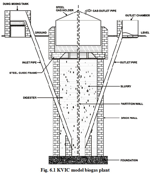
These plants are commonly known as KVIC (Khadi Village and Industrial Commission) plants and were standardized in 1962 and are used widely even now. These plants have an underground well-shaped digester having inlet and outlet connections through pipes located at its bottom on either side of a partition wall. An inverted drum (gas holder) made of mild steel is placed in the digester which rests on the wedge shaped support and the guide frame at the level of the partition wall and moves up and down along a guide pipe with the accumulation and use of gas. The weight of the drum applies pressure on the gas to make it flow through the pipelines to the points of use. The different components of KVIC biogas plants are shown in Fig. 6.1.
The gasholder alone is the costliest component which accounts for about 40% of the total installation cost of biogas plant. It also needs to be painted regularly for protecting it against corrosion. These plants can be of any size to cater the needs of the users.
Fixed dome type model biogas plant
In spite of increasing popularity and acceptance of the KVIC biogas plants by the public, these biogas plants by and large beyond the reach of most rural people because of high increasing cost, short life of steel drum. So, there was an apparent need to have alternative inexpensive design to bring it within the reach of the rural population. Due to these reasons, the floating drum type biogas plants have been replaced with fixed dome biogas plants. These are :
i. Janta Model Biogas Plants
ii. Deenbandhu Model Biogas Plants
Janta model biogas plant
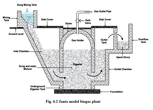
This is the first fixed-dome biogas plant was introduced in the form of the Janta Model Biogas Plant by Gobar Gas Research Station, Ajitwal in 1978. The main feature of this model is that the digester and the gas holder are integrated parts of brick masonry structure. The digester is made of a shallow well having a dome-shaped roof on it. The inlet and outlet tanks are connected with the digester through large chutes which are called displacement chambers. The gas pipe is fitted on the crown of the masonry dome and there is an opening on the outlet wall of the outlet displacement chamber for the discharge of spent digested slurry. The size of these plants is limited to 15 m3 par day. The different components of Janta Model Biogas Plant are shown in Fig. 6.2.
Deenbandhu model biogas plant
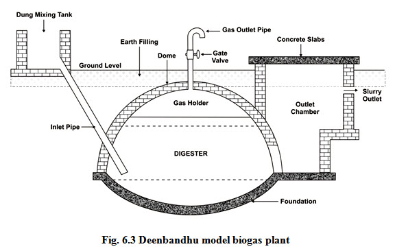
Deenbandhu model biogas plant was developed by AFPRO (Action for Food Production, New Delhi) in 1984. The world Deenbandhu is meant as the friend of the poor. This plant is designed on the principle that the surface area of biogas plants is reduced (minimized) to reduce their installation cost without sacrificing the efficiency of the plant. The design consists of segments of two spheres of different diameters, joined at their bases. The structure thus formed act as the digester as fermentation chamber as well as the gas storage chamber. The higher compressive strength of the brick masonry and concrete makes it preferable to go in for a structure which could always be kept under compression. A spherical structure loaded from the convex side will be under compression and therefore, the internal load will not have any residual effect on the structure.
The digester is connected with the inlet pipe and the outlet tank. The upper part above the normal slurry level of the outlet tank is designed to accommodate the slurry to be displaced out of the digester with the generation and accumulation of biogas and is called outlet displacement chamber. The size of these plants is recommended up to 6 m3 par day. The different components of Deenbandhu Model Biogas Plant are show in Fig. 6.3.
Comparison among KVIC, Janta and Deenbandhu biogas plants
Comparison among the above mentioned biogas plants is explained in Table 6.1
Table 6.1 Comparison between KVIC, Janata and Deenbandhu biogas plants
|
Sr. No. |
KVIC |
Janata |
Deenbandhu |
|
1. |
The digester of this plant is a deep well shaped masonry structure. In plants of above 3m3 capacity a partition wall is provided in middle of the digester. |
Digester of this plant is a shallow well shaped masonry structure, No partition wall is provided. |
Digester is made of segments of two spheres: one for the bottom and other for the top. |
|
2. |
Gas holder is generally made of mild steel. It is inverted into the digester and goes up and down with formation and utilization of gas. |
Gas holder is an integral part of the masonry structure of the plant. Slurry from the gas storage portion is displaced out with the formation of gas and comes back when it is used. |
The structure described above includes digester and the gas storage chamber. Gas is stored in the same way as in the case of Janata plants. |
|
3. |
The gas is available at a constant pressure of about 10 cm of water column. |
Gas pressure varies from 0 to 90 cm of water column. |
Gas pressure varies from 0 to 75 cm of water column. |
|
4. |
Inlet and outlet connections are provided through A.C pipes |
Inlet and outlet tanks are large masonry structures designed to store the slurry displaced out of the digester with the formation of gas. |
Inlet connection is through A.C pipe. Outlet tank is a large masonry tank designed to store slurry displaced out of the digester with the formation of gas. |
|
5. |
Gas storage capacity of the plant is governed by the volume of gas holder and is 50% of gas produced per day. |
It is the combined volume of inlet and outlet displacement chambers and is 50% of gas produced per day. |
It is the volume of outlet displacement chamber and is 33% of gas produced per day. |
|
6. |
The floating mild steel gas holder needs regular care and maintenance to prevent the gas holder from getting worn out because of corrosion. It also has short life span. |
There is no moving part and hence no recurring expenditure. It also has long working life. |
There is no moving part and hence no recurring expenditure. It also has a long working life. |
|
7. |
Installation cost is very high. |
It is cheaper than the KVIC type plants. |
It is much cheaper than KVIC and Janata type plants. |
|
8. |
Digester can be constructed locally but the gasholder needs sophisticated workshop facilities. |
Entire plant can be built by a trained mason using locally available materials. |
Entire plant can be built by a trained mason using locally available materials. |
Working of biogas plant
Initially the digester is filled with a uniformly premixed mixture of dung and water (1:1 ratio) and the digester may be filled in three or four days or more time depending upon the availability of the dung. In order to facilitate gas production, addition of 5 to 10% inoculums, taken from a running biogas plant, will hasten the process by three to four days. In case no inoculums are available, sewage sludge can also be added. The first two or three installments of gas will not burn because of excessive CO2.
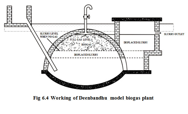
When the cattle dung is used as feed stock, the biogas plant is to be filled with a homogenous slurry made from a fresh dung and water in a ratio of 1:1 up to the level of the second step in the outlet chamber (Fig. 6.4).
As the gas generates and accumulates in the empty portion of dome of the biogas plant, it presses down the slurry of the digester and displaces it into the outlet chamber. The slurry level in the digester falls, whereas in the outlet chamber, it starts rising with the formation of gas. This fall and rise continues till the level in the digester reaches the upper end of the outlet opening, and at this stage, the slurry level in the outlet chamber will be at the slurry outlet. Any gas produced after this stage will escape through the outlet chamber till the gas is not used.
When the gas is used, the slurry which was earlier displaced out of digester and stored in the outlet chamber begins to return into the digester. The difference in levels of slurry in digester and the outlet chamber exerts pressure on the gas which makes it flow through the gas outlet pipe to the points of utilization of biogas.
Last modified: Wednesday, 29 January 2014, 11:13 AM