Site pages
Current course
Participants
General
Module 1. Introduction to by-products and waste ge...
Module 2. Waste management concepts
Module 3. Direct combustion of solid waste
Module 4. Thermo-chemical conversion of solid waste
Module 5. Bio-chemical conversion of solid waste
Module 6. Solid waste management
Module 7. Effluent treatment and disposal
Module 8. Presence of typical chemicals
19 April - 25 April
26 April - 2 May
Lesson 8.
Biogas as a lighting fuel
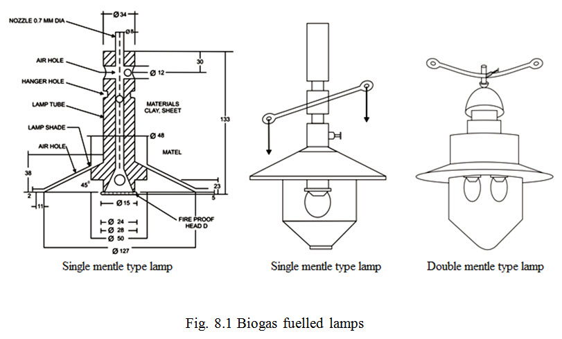
Biogas can be fed into any gas lamp using a mantle for lighting. Biogas lamp consists of nozzle, an air inlet, mixing chamber, mantle and glass globe. In biogas lamp, when gas is burnt, mantle of the lamp glows which causes lighting. Mantle in biogas lamp is similar to one used in a ‘Coleman’ or propane lamp. Mantle is normally made of Ramie fibre (which is also used in making glass cloth and liner) and is coated with thorium nitrate solution. While burning, the Ramie fibre reduces to ash forming a layer of thorium dioxide which emits dazzling white light at high temperatures. Nozzle of this burner is of the size of a needle point having 0.5 to 0.7 mm diameter. The other end of the nozzle is connected to gas supply hose which is linked to a biogas plant. Biogas emerges out from the nozzle at very high temperature forming low pressure area around it. As biogas passes through the nozzle, air is allowed to be drawn into the mixing chamber to freely mix with it. Brightness of biogas lamp mainly depends on factors like gas pressure, and relative proportion of gas and air which is about 1:10 and thoroughness in mixing. For achieving bright intensity, nozzle needle to be adjusted by trial and error. Low gas pressure causes poor light intensity, but higher pressure though it improves brightness but tends to lower mantle-life. Biogas lamps can be either suspended (hanging type) or put on table (standing type). As weight of biogas is almost half as that of air and as hot air flows upwards, brightness of a standing biogas lamp is somewhat greater than that of a hanging type. Biogas lamps are generally designed to produce 100 candle power (C.P.) and consume 0.11 to 0.15 m3 biogas per hour.
In India, the biogas lamps are designed with single or double mantles. Both single and double mantel types can be further classified as internal or external types. An internal mantle lamp has a simple cover and is designed to produce 100 candle power (C.P.) which is equivalent to light intensity of 60 watts electric bulb. An external single mantle lamp has an outside protective cover to safeguard it from rain and wind and is also capable to produce same light intensity of 100 candle power. Designs of these two lamps are shown in Fig. 11.5 which works at gas pressure of 7.0 to 8.5 cm water column. A double mantle lamp can also be of both internal and external type. The internal type is fitted with a simple cover and can produce upto 100 candle power. The two mantle external type is equipped with a special cover to protect it from rain and wind and is also capable to produce 100 candle power (C.P.).
As for the starting sequence of the lamp, after opening gas cock and regulator, mantle is lit to light the lamp. Lamp can be turned-off by operating the gas cock. Regulator is adjusted for achieving requisite brightness. For preventing the possibility of any hazard, the lamp should be lit by bringing the match-stick close to the mantle either via the hole in the base of glass globe or via the reflector after opening it.
Biogas for running dual fuel engines
Biogas as an engine fuel offers several advantages, biogas being a clean fuel causes smokeless combustion and reduced contamination of engine oil. It also reduces deposits on piston and combustion chamber. As gas needs is considerable, large capacity biogas plants are needed to supply gas for running IC (Internal Combustion) engines. It is to be noted that, even a 5 H.P. engine for 8 hourly operation requires gas supply from a biogas plant of 15 m3/day capacity. Community biogas plants with a gas output of 50 m3 per day are generally used to drive biogas fuelled electricity generating sets.
Normal consumption rate of biogas for running IC engines is 0.45 to 0.54 m3/hour/H.P. or 0.60 to 0.70 m3/hour kW if used for power generation. Biogas pressure is found to vary from 2.5 to 10.0 cm water column. If an engine consumes 0.50 m3 of biogas/hour/H.P., then quantity of engine consumes 0.50 m3 of biogas/hour/H.P., then quantity of gas needed for running a 10 H.P. engine for 10 hour operation per day becomes.
= (0.50 m3/hour/H.P.) x 10 x 10 = 50 m3.
Norms of biogas consumption for operating different capacity engines on dual-fuel are given in Table 8.1. These ratios are based on 8 hourly operation with 75 per cent plant efficiency with biogas consumption rate being 0.257 m3/H.P./ hour having 50 per cent diesel replacement with biogas, although replacement of diesel can be as high as 80 per cent.
Table 8.1 Rates of biogas consumption for operating different capacity engines on dual-fuel
|
S. No. |
Engine rating H.P. |
Biogas consumption (m3/day) |
Capacity of plant to supply biogas (m3/day) |
|
1. |
5 |
360 |
480 |
|
2. |
10 |
720 |
960 |
|
3. |
15 |
1080 |
1440 |
|
4. |
20 |
1440 |
1920 |
During the operation of an diesel engine, it is noted, when the piston moves downward during first stroke, then the inlet value opens and the fresh air is filled in the cylinder which enters through the air cleaner. In the second stroke, the piston moves upwards, then both the valves are closed and the air which is already entered in the cylinder is being compressed upto the ratio 17:1. Due to this compression, temperature of air is very much raised. After that the diesel is being injected into this hot air which catches fire and the piston again moves downward due to the high pressure of air. In the fourth stroke, the exhaust valve opens and the fuel gases are exhausted outside due to upward movement of the piston. Thus it is very clear from the operation of diesel engine that small quantity of diesel should be must for ignition. Due to this reason, a dual-fuel engine is first started with diesel fuel only. After it has attained normal running for some time, biogas choke is opened to admit gas into the combustion chamber. Biogas combustion can be controlled by adjusting the choke. In a steady engine operation, dual-fuel achieves nearly 75 per cent saving in diesel consumption. For stopping dual-fuel engine, biogas choke should be stopped first followed by throttle.
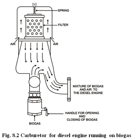
To run diesel engine on biogas, the biogas pipe is joined with the air cleaner of the engine to prepare the mixture of biogas and air. In the first stroke of the piston, the engine sucks biogas and air and it catches fire after injecting the diesel by the nozzle. A special and simple instrument shown in Fig. 8.2 can also be used to prepare the mixture of biogas and air and is joined with the diesel engine at modified inlet. The control of biogas is being done with the help of gate valve attached to this instrument.
 Methane, the lightest organic gas, has two fundamental drawbacks to its use in heat engines: it has a relatively low fuel value and it takes nearly 34450kPa pressure to liquefy it for easy storage, (2.48 m3 of methane gas can be converted to 4.55 litre of liquid methane). So a great deal of storage of methane is required for a given amount of work. For comparison, propane liquefies around 1722.5kPa.
Modified petrol engines
A petrol engine can be modified to run on biogas by drilling a hole in the carburetor near the choke. A tube is then inserted which is connected to the gas through a control valve. The engine is to be started on petrol and then switched on to run on biogas only.
In some cases, gas is admitted into the inducted air through a cam operated valve. A governor controlled disc regulates the quantity of gas admitted in accordance with the engine output. The governor also throttles the air supply so that the gas air mixture is within the ignition limits.
Typically a 4-stroke single cylinder 1 BHP engine running at 1800 rpm needs a biogas supply line of 9 mm diameter and gas pressure of 50 to 100 mm of water. The power developed is 85% of the older rating. The gas consumption is 0.51 m3/h at full load and air to fuel ratio is 5.83 :1 at full load and 5.75:1 at normal load. The engine dissipates more heat than a conventional engine and the cooling system must be preferably water cooled.
Modifications
The conversion of SI engine for operation on biogas includes provisions for the entry of biogas , throttling of intake air and advancing the ignition timing. Biogas can be admitted to a stationary SI engine through the intake manifold and an air flow control valve can be provided on the air cleaner pipe connecting the air cleaner and carburetor for throttling of intake air. In this case the intake air is required to be manually throttled in the initial stage.
Modified diesel engines (The dual fuel engine)
A diesel engine can be easily converted to run on 80 to 90% biogas and 20% to 10% diesel by feeding the gas in between the air intake and the engine. After the engine is started on diesel oil, the gas valve is opened gradually and the engine’s governor automatically reduces the intake of diesel oil. Since the compression of the gas-air mixture is not sufficient to produce the temperature required for ignition, there is no danger of pre-ignition.
CI engine can operate on dual fuel and the necessary engine modifications include provision for the entry of biogas with intake air, advancing the injection timing and provision of a system to reduce diesel supply.
The entry of biogas and mixing of gas with intake air can be achieved by providing a mixing chamber below the air cleaner which facilitates thorough mixing of biogas with air before entering into the cylinder. The arrangements largely used in stationary engines commercially available in India. The capacity of mixing chamber may be kept equal to the engine displacement volume. The pilot injection of diesel in the cycle is required to be advanced for smooth and efficient running of engine on dual fuel.
Biogas for electricity generation
Biogas can be used to produce electricity by coupling a dual-fuel engine to an asynchronous generator. Based on results of several studies carried out. 1 kWh of electricity can be generated from 0.75 m3 of gas which can light 25 electric bulbs of 40 w rating whereas 0.75 m3 of gas if directly burnt can light only 7 biogas lamps for one hour. Hence it is advantageous to first generate electricity and then light larger number of electric bulbs. In China asynchronous generators of 3, 3.5 and 7.5 kW rating coupled to biogas-based IC engines are commonly used. However, electricity generation from biogas is economical only when gas is supplied by large community plants but it requires high initial capital investment. Decentralized power systems can be cost-effective especially when they minimize transmission and distribution costs. For cost-effective system, unit cost of biogas-based electricity should be less than supplied by the electricity boards.
Biogas in boilers and water heaters
Biogas successfully fueled the boiler that heated the digester chamber. Preliminary tests were made of its usefulness as fuel for a household-type water heater and for operating spark-ignition and compression-ignition internal-combustion engines.
The gas-fired cast-iron boiler was of commercial manufacture, of a type that would normally be fueled with LP gas. Several changes were required to prepare the unit for fueling with biogas:
The diameter of the nozzle orifice was increased. The heating value of biogas is only 30 per cent that of LP gas and only 60 per cent that of natural gas, and line pressures were less with biogas than with LP gas. Consequently, the diameter of the burner nozzle orifices was enlarged approximately 70 per cent of biogas utilization.
Air supply to the burner was decreased. The air-inlet ports had to be almost completely closed, which required special covers for the air inlets.
Moisture was removed. A system of cooling and heating the gas in combination with condensate traps facilitated delivery of the gas to valves and orifices without risk of condensation in these narrow channels. pressure-regulator valves were kept warm to prevent condensation.
An independent fuel source (LP gas) was used for the pilot light. This was because the quality and supply of biogas may not be totally reliable. The pilot light required approximately 0.45 kg LP gas per day.
A 40-gal (150-liter) water heater was operated experimentally, using biogas as fuel. This test indicated that a gas consumption of 40 liter/min of water from 10 to 65°C. This corresponds to a thermal efficiency of 65 per cent, compared to a rated efficiency of 70 per cent. Further adjustment of the burner would probably improve its performance when fueled with biogas.
Since well-adjusted and fully loaded boilers and other water-heating devices may be assumed to have 70 per cent efficiency on biogas, as well as on other gaseous fuels, the fuel consumption for a water heater can be calculated from the relationship that 3.2 m3 of biogas 62 MJ will heat 190 liter of water from 50 to 10 to 65°C. In a home-heating system, 5.2 m3/h of biogas would give a rated (input) heating capacity of 29 kW.
Biogas use in stationary power plants
Biogas can be used in both spark ignition engines and compression ignition engines. The choice of the engine depends on the following factors:
(a) If the gas supply is assured, a S.I. engine can be used.
(b) If the gas supply is not assured, a C.I. engine with dual fuel operation can be used. This engine can run completely on diesel when gas is not available.
Biogas can be used in stationary power plants in the following modes :
(i) In a spark ignition engine by using a higher compression ratio with magneto ignition and modifying the carburetor system.
(ii) In a compression ignition engine with gas injection and pilot diesel injection. This requires biogas at high pressure. This is not generally used.
(iii) As a dual engine with diesel and biogas. Also dual fuel engine with petrol and biogas can be used, but this require relatively greater modifications.
(iv) In dual fuel gas turbines.
The following points be noted:
(a) Purification of gas by separation of H2S prevents corrosion. Removal of H2S prolongs engine life. Exhaust would be free of sulphur compounds.
(b) Removal of CO2 by scrubbing the gas through lime water improves the calorific value by 30% on volume basis. Volumetric efficiency would improve and also higher specific output can be obtained.
(c) Gas burn carburetor for controlling intake of gas and air would be preferable.
(d) Regulation of engine cooling water flow rate would be desirable as the engines dissipate more heat than conventional engines.
(e) Use of biogas receiver bag for maintaining a constant pressure and flow rate may be considered. This consists of a cylindrical tube of 300 mm length and 75 mm diameter with a half return valve on the outlet side and a wire netting ball at the constriction point of cylinder outlet tube.
(f) Slow speed engines should be preferred.
(g) Ignition/injection timing advance to be set optimally.
Biogas in gas turbines
The main advantage of the use of gas turbines is that the capital cost is considerably lower compared to reciprocating engines-particularly when used aircraft engines whose normal flying duty is over are utilized. There are additional advantages of easy installation, modular maintenance, quick starting and reliable operation. National Aerospace Laboratory has studied the applications of Rolls Royee ‘Dart’ Engines used by IAF and Indian Airlines to provide mechanical energy for 1.0 to 2.5 MW electrical generators. These can be operated on dual fuels [biogas + diesel or kerosene]. This approach seems to be promising.
The production of electrical energy only by biogas fuel is not economical. However, cogeneration with I.C. engine connected with a generator and with waste heat recovery would be economical. The waste heat recovered can be cycled for digester heating.
Biogas in refrigerators
Biogas can be used in absorption refrigeration system without any problems as long as assured gas supply for burner is available. For a Refrigerator of 230 litres capacity, the biogas consumption will be approximately 0.044 m3/l.
Particular problems also arise with biogas operated refrigerators. The composition of biogas varies substantially from day to day. The gas pressure fluctuates excessively with the amount of gas stored even in a floating drum plant. Special, stable-burning jets are therefore needed-especially if the refrigerator is thermostatically controlled and the flame burns only when required. On every ignition there is a risk of the flame going cut. Gas will then discharge without burning. The gas supply must therefore automatically be cut off if the flame goes out.
Small scale dairies handling 500 litres of milk per day seems to be feasible units for the rural setup. It is assumed that water is available in abundance and cooling of the milk from pasteurizing temperature of about 70°C to, say, 35oC can be done with the available cold water. Heat to be removed by water (taking the specific gravity and specific heat of milk as 1.03 and 0.95 ) is 500 x 1.03 x 0.95 x 35 = 17124 kcal.
For a raise in temperature of water of 5oC, the amount of water necessary = 17124/5 = 3425 kg.
Taking 4hrs.period for cooling, the required water flow rate = 3425/4 = 856 kg/hr.
For a 10m delivery head of water and a pump efficiency of 50%, the shaft HP required for the circulation pump = 856 x 10/(60x4500x0.5) = 0.06.
To cool the milk from 35oC to 3oC heat to be removed
= 500 x 1.03 x 0.95 x (35 - 3) = 15656 kcal.
Assuming 30% heat loss actual heat to be removed at the evaporator = 20 353 kcal.
Considering 8 hrs. operating time the refrigerating capacity needed
= 20353/(8x60x50) = 0.848 tons.
For a 3 m x 3m x 3m walk in cold storage the approximate cooling required would be 0.6 tons of refrigeration.
Total cooling capacity needed for the dairy = 1.448 tons. Hence the engine power needed for the dairy plant is approximately 2 hrs. Biogas out put needed for a dual fuel diesel engine for the above purpose = 4 m3/day. For a spark ignition engine running totally on biogas the gas out put needed is 6.4 m3/day. This would necessitate output from over 15 cattle heads.
Last modified: Wednesday, 29 January 2014, 11:49 AM