Site pages
Current course
Participants
General
MODULE 1.
MODULE 2.
MODULE 3.
MODULE 4.
MODULE 5.
MODULE 6.
MODULE 7.
MODULE 8.
MODULE 9.
MODULE 10.
LESSON 19. Design of Doubly Reinforced Sections
19.1 INTRODUCTION
Three main types of problem may be put in case of design of doubly reinforced section.
Type I. In this type following information is given in the question itself.
-
The dimensions of the section.
-
The area of reinforcement in tension and compression.
-
The maximum permissible stresses in concrete and steel.
It is required to determine the moment of resistance of the section.
Procedure to solve: The solution of this type of problem involves the steps given below:
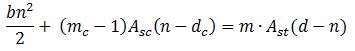
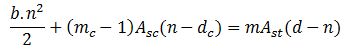
1.Find the position of the actual neutral axis of the section by equating the moment of the areas of the concrete and equivalent area of compression steel to the moment of the equivalent concrete area of steel in tension about the neutral axis. This is given by the equation
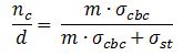
2.Find the position of the critical neutral axis (nc) by the equation
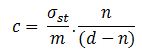
3. If the actual neutral axis lies above the critical neutral axis, the stress in tensile steel attains its maximum permissible value (i.e. t = ) first and the corresponding value of stress in concrete at top (c) is given by
and stress in concrete surrounding steel in compression is given by
![]()
Having known the values of c and c’, the moment of resistance of the section can be obtained by taking the moments of all the forces about the tensile steel. This is given by the equation.
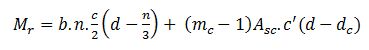
It may be noted that the value of (c) in the expression is different from permissible compression stress in concrete i.e.,.
(iv) If the actual neutral axis lies below the critical neutral axis or coincides with it, the stress in concrete attains its maximum permissible value first and hence the moment of resistance of the section is obtained by the equation.
![]()
Type II. In this type following information is given:
-
The dimensions of the section.
-
Area of reinforcement in tension and compression.
-
The modular ratio and the maximum bending moment to which the section is subjected to.
It is required to find out the stresses developed in concrete and steel.
Procedure to solve: The solution of this type of problem involves the steps given below.
1.Find the position of N.A. by the equation
![]() ...(3.2)
...(3.2)
2.Find stress in concrete (c’) surrounding compression steel by the equation
![]() ...(3.4)
...(3.4)
3.To find c, equate the moment of resistance of the doubly reinforced section to the external bending moment (M). This is given by
![]()
In this equation except c everything is known and hence c can be worked out.
4.Find the stress in steel by adopting the value of c as obtained in step (iii) in the formula.
![]()
Type III. In this type of problem, the dimensions of the section, the maximum permissible stress in concrete and steel, and the bending moment to which the section is subjected to are given and it is required to design the section.
Procedure to solve: The solution of this type of problem is given in -----------
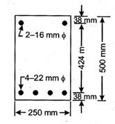
Example 19.1 Find the moment of resistance of a beam 250 mm x 500 mm in section if it is reinforced with 2 bars of 16mm dia, at top and 4 bars of 22 mm dia. At the bottom each at an effective cover of 38 mm. Safe stresses in the materials are:
σcbc= 5 N/mm2
σst = 140 N/mm2
m = 19
Solution Equating the moments of the area of concrete and equivalent concrete area of compression steel to the moment of the equivalent concrete area of steel in tension about the neutral axis, we get
From the given data, we have
Subsututing the values in the above equation, we have
or 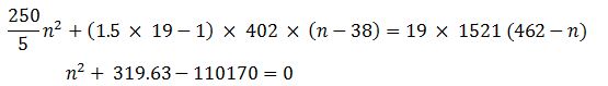
which gives n=208.58mm
The value of critical neutral axis can be obtained by the expression
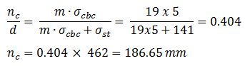
Since the actual neutral axis lies below the critical N.A., the stress in concrete will reach its maximum permissible value of ![]() first.
first.
Hence the stress in concrete surrounding compression steel is given
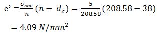
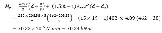
The moment of resistance of the beam is given by
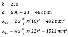
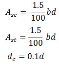
Example 19.2 A reinforced concrete beam is b mm wide and d mm deep upto the centre of the tensile reinforcement. The beam is doubly reinforced. The tensile reinforcement and the compressive reinforcement are each equal to 1.5%. The compressive steel is placed at an effective cover of 0.1 d from the top face of the beam. Calculate the moment of resistance of the beam. The following data being given:
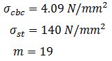
Solution From the given data:
Equating the moment of equivalent areas about the neutral axis, we get
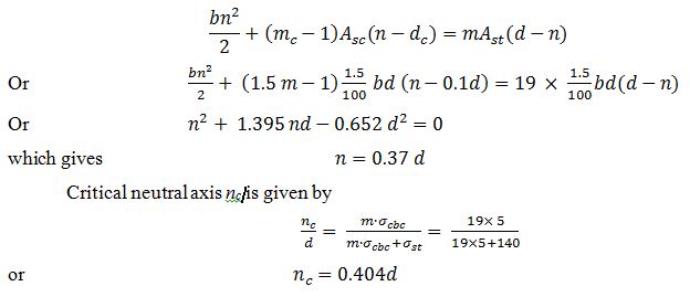
The actual neutral axis lies above critical neutral axis hence the stress in steel reaches its maximum permissible value of 140 N/mm2 first.
Hence the stress in concrete and stress in concrete surrounding compression steel shall calculated as under
![]()
or ![]()
Similarly ![]()
or ![]()
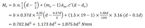
The moment of resistance of the section is given by
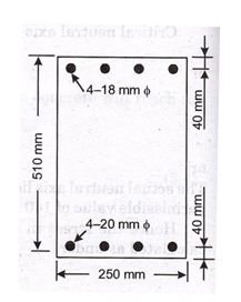
Example 19.3. A doubly reinforced concrete beam is 250 mm wide and 510 mm deep to the centre of tensile steel reinforcement. The compression reinforcement consists of 4 Nos. 18 mm dia. bars placed at an effective cover of 40 mm from the compression edge of the beam. The tensile reinforcement consist of 4 Nos. 20 mm dia. bars. If the beam section is subjected to a bending moment of 85 kNm, calculate the stresses in concrete and tension and compression steel. Adopt m = 11.
Solution: Area of tensile reinforcement
![]()
Area of compression steel
![]()
Equating the moments of the equivalent areas about N.A., we get
![]()
or ![]()
or ![]()
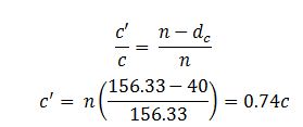
which gives n=156.33 mm.
Let the maximum stress developed in concrete be c. The stress in concrete surrounding compression steel or c΄ is given by
Equating the moment of resistance of the beam to the external bending moment, we get
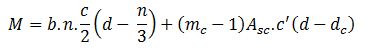

=14.44 x 10⁶ c
or ![]()
and ![]()
Stress in compression steel = ![]()
![]()
Stress in tensile steel is given by
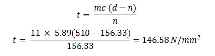
Last modified: Saturday, 5 October 2013, 8:42 AM