Site pages
Current course
Participants
General
MODULE 1.
MODULE 2.
MODULE 3.
MODULE 4.
MODULE 5.
MODULE 6.
MODULE 7.
MODULE 8.
MODULE 9.
MODULE 10.
LESSON 20. Theory of T-Beams
20.1 INTRODUCTION
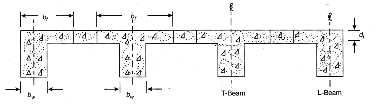
In this type of beam, the R.C.C. floor or roof slab is case monolithic with the beam as shown in Fig. 20.1. The stirrups and the bent up bars of the beam extend into the slab and a portion of the slab acts with the beam for resisting compressive stresses. This results in increasing the moment of resistance of the beam. The slab cast integrally with the beam is called flange of the beam and the part of the beam projecting below the slab or flange is known as rib or web of the beam.
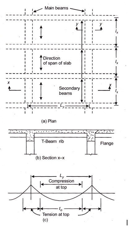
In case of simply a supported beam the bending moment is of sagging nature throughout its length. Hence the slab forming the flange of the T-beam is subjected to compression all along the span and the beam behaves as a T-beam throughout the span. On the other hand in case of a continuous beam the bending moment is of sagging nature at mid-span and it is of hogging nature at the supports as shown in Fig. 20.2. In the span portion the beam top remains under compression between the points of zero bending moment and hence the contribution of flange remains effective within the mid-length ( of the beam upto the points of zero bending moment. This length can be assumed to be equal to 0.7 times the effective span and the beam thus behaves as T-beam only for this length. Beyond the points of zero BM and over the supports, the flange of the beam is subjected to tension.
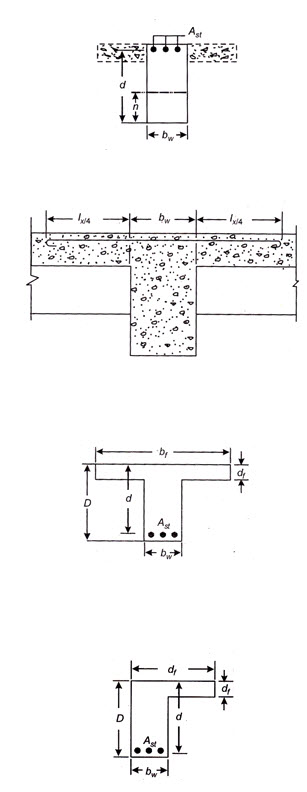
Since the tensile resistance of concrete is totally ignored in our basic assumptions, the availability of slab as flange of the beam in tension zone of the beam is of no use. Hence the T-beam behaves as a rectangular beam over support (refer Fig. 20.3). Since the depth of the beam is fixed by taking advantage of the compressive resistance of concrete in flange of the T-beam, it is obviously less than the depth required for a rectangular beam. Thus the section of the beam at the supports is restricted in its dimensions and is usually designed as doubly reinforced section.
The slab forming the flange of the T-beams may be spanning either transverse to the beam or it may be spanning parallel to it. However, when the slab spans parallel to the beam (i.e. the main reinforcement of the slab is parallel to the beam) adequate reinforcement should be provided transverse to the beam throughout its length upto a distance of on either side of the rib of the beam near the top face of the flange as shown in Fig. 20.4.
As per IS: 456 – 1978, the area or such reinforcement should not be less than 60 per cent of the area of main reinforcement provided at mid-span of the slab.
20.2 DIMENSIONS OF A T-BEAM
Figure 20.5 shows the important dimensions of a T-beam which are as under :
(1) Thickness of the flange (df). This is equal to the overall depth of the slab forming the flange of the T-beam.
(2) Breadth of web (bw). This is the breadth of the beam projecting below the slab. The breadth of web should be sufficient to accommodate the tensile reinforcement in the beam with suitable spacing between the bars.
(3) Overall depth of beam (D). The overall depth of the beam depends upon the span as well as loading conditions. In case of simply supported beams it may be assumed to be 1/12 to 1/15 of the span. In case of continuous beam, the assumed overall depth may be taken as 1/15 to 1/20 of span for light loads; 1/12 to 1/15 of span for medium loads and 1/10 to 1/12 of span for heavy loads.
(4) Effective width of flange (bf). It is obvious that the portion of slab (acting as flange) away from the beam web is stressed lesser than the portion immediately above the web. In order to simplify calculations certain width of flange (which normally works out to be less than actual width) is considered to be under uniform stress and hence effective for resisting compression in the beam. This width is termed as effective width of flange. The effective width of flange mainly depends upon the span, breadth of web and the thickness of slab acting as flange.
The code IS : 456-1978 stipulates that the effective width of flange may be taken as under but in no case the effective width of flange shall be greater than the breadth of web plus half the sum of the clear distances to the adjacent beams on either side.
Effective width of flange:
(a) For T-beams
\[{b_f}=\frac{{{l_o}}}{6}+{b_w}+6{d_f}\]
(b) For L-beams
\[{b_f} = \frac{{{l_o}}}{{12}} + {b_w} + 3{d_f}\]
(c) For isolated beams, the effective flange width shall be obtained as below but in no case greater than the actual width.
(i) In case of T-beam,
\[{b_f} = \frac{{{l_o}}}{{12}} + {b_w} + 3{d_f}\]
(ii) In case of L-beams (refer Fig. 20.6),
\[{b_f}=\frac{{0.5{l_o}}}{{\left({\frac{{{l_o}}}{b}}\right)+4}}+{b_w}\]
where
effective width of flange
= distance between the points of zero moments in the beam
= breadth of web
= thickness of flange
= actual width of the flange. and
Note. For continuous beams and frames may be assumed as 0.7 times the effective span.
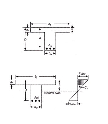
20.3. LOCATION OF NEUTRAL AXIS
The depth of the neutral axis is determined by equating the moment of area of concrete in compression to the moment of equivalent area of steel in tension. Depending upon the thickness of the flange and the bending moment applied to the beam, the neutral axis may lie (i) within the flange or (ii) it may lie outside the flange. The two cases are treated separately.
Case I. Neutral axis within the flange: In this case N.A. may be located exactly in the same manner as in case of singly reinforced sections (refer Fig. 20.7). N.A. in this case is worked out by the expression.
\[(b_f n^2 )/2= m.A_s t(d-n)\]
Case II. Neutral axis below the flange (refer Fig. 20.8): If the value of n as obtained from the above equation works out to be more than the thickness of flange it will have to be re-worked out by equating the moments of the compressive and tensile areas about N.A. by the equation
\[b_f d_f (n-d_f /2)+b_w(n - d_f )^2 /2 = m.A_s t(d - n)\]
In this expression the term \[{b_w}\frac{{{{\left( {n-{d_f}}\right)}^2}}}{2}\] is normally very small and it is considered desirable to ignore it.
Thus the simplified form of equation becomes \[{b_f}{d_f}\left( {n - \frac{{{d_f}}}{2}} \right) = m.{A_{st}}(d - n)\]
If however, the maximum stresses in concrete and steel are given, the neutral axis is worked out by use of the relation:
\[\left({\frac{n}{{d-n}}}\right)=\frac{{{\sigma _{cbc}}}}{{\frac{{{\sigma _{st}}}}{m}}}=\frac{{m.{\sigma _{cbc}}}}{{{\sigma _{st}}}}\]
20.4. LEVER ARM OF T-BEAM
If c and cs be the compressive stress in the top and bottom edges of the flange respectively and be the distance of C.G. of the total compression below the top edge, then from the trapezoidal stress diagram shown in Fig. 20.8, we have
\[\bar y=\left({\frac{{c+2{c_s}}}{{c+{c_s}}}}\right)\frac{{{d_f}}}{3}\]
where \[{c_s}=\frac{{c\left({n-{d_f}}\right)}}{n}=\frac{{{\sigma _{cbc}}.\left( {n - {d_f}}\right)}}{n}\]
Lever arm of the T-beam \[a=d-\bar y\]
20.5 MOMENT OF RESISTANCE
The moment of resistance of a T-beam is determined by taking the moment of the total compression in the beam about the C.G. of the tensile reinforcement.
The moment of resistance (Mr) = Total compression x lever arm.
(i) If the neutral axis lies in the flange ![]()
(ii) If the neutral axis lies in the web ![]()
20.6 MOMENT OF RESISTANCE TAKING COMPRESSION IN WEB INTO ACCOUNT
The moment of resistance of a T-beam shall normally be worked out by use of above equations. If, however, it is specifically desired to consider compression in web as well, the moment of resistance in that case will comprise of the following.
(i) Moment of resistance due to compression in flange. Let it be denoted by M1 and
(ii) Moment of resistance due to compressive force in web. Let it be denoted by M2
\[{M_r}={M_1}+{M_2}\]
Now, \[{M_1}={\rm{Totalcompressioninflange}}\times{\rm{leverarm}}\]
\[ ={b_f}.{d_f}\left({\frac{{c+{c_s}}}{2}}\right)(d-\bar y)\]
and \[{M_2} = {\rm{Totalcompressioninweb}} \times {\rm{leverarm}}\]
\[= {b_w}\left( {n - {d_f}} \right)x\frac{{{C_s}}}{2}\left[ {d - \left( {{d_f} + \frac{{n - {d_f}}}{3}} \right)} \right]\]
\[{M_r}={b_f}.{d_f}\left({\frac{{c +{c_s}}}{2}}\right)\left({d-\bar y}\right)+{b_w}\left( {n-{d_f}}\right)\times\frac{{{C_s}}}{2}\left[{d-\left({{d_f}+\frac{{n-{d_f}}}{3}}\right)}\right]\]
20.7 ECONOMICAL DEPTH OF A T-BEAM
To solve an expression for economical depth of T-beam proceed as under:
Let
\[{R_{conc}}\]=cost of concrete per cubic centimeter
\[{R_{steel}}\]= cost of steel per cubic centimeter
and r = ratio of the cost of steel to cost of concrete
\[r=\frac{{{R_{steel}}}}{{{R_{conc}}}}\]
The volume of concrete in the flange remains fixed and is not considered in the calculation.
Let
\[{d_t}\] = the cover measured below the centre of the tensile reinforcement in the T-beam
\[d\] = effective depth of the beam
\[{d_f}\]= overall depth of the flange
\[{b_w}\]= breadth of the flange
and \[{A_{st}}\]= Area of tensile reinforcement
Consider 1 cm length of the T-beam web.
Volume of concrete per cm length of web \[={b_w}(d-{d_f}+{d_t})\]
Cost of concrete in the web per cm length \[={b_w}(d-{d_f}+{d_t}){R_{conc}}\]
Similarly cost of steel per cm length of web \[={A_{st}}x{R_{steel}}\]
\[= r.{R_{conc}}.{A_{st}}\] \[\left[ {\frac{{{R_{steel}}}}{{{R_{conc}}}} = r} \right]\]
Since \[{A_{st}}=\frac{M}{{j.d.{\sigma _{st}}}}\]
Cost of steel per cm length \[= r.{R_{conc}} \times \frac{M}{{j.d.{\sigma _{st}}}}\]
Let R be the total cost per cm length of the beam web
\[R ={R_{conc}}.{b_w}\left({d-{d_f}+{d_t}}\right)+{R_{conc}}\frac{M}{{j.d.{\sigma _{st}}}}\]
\[={R_{conc}}.\left[{{b_w}\left({d-{d_f}+{d_t}}\right)+\frac{M}{{j.d.{\sigma _{st}}}}}\right]\]
In this expression,\[{b_w},{d_f}\]and are fixed and d is the only variable. Then for the cost to be minimum\[\frac{{d(R)}}{{d(d)}}\] should be equal to 0
\[\frac{{d(R)}}{{d(d)}}=0={R_{conc}}\left[{{b_w}-\frac{{rM}}{{j.{d^{2.}}{\sigma _{st}}}}}\right]\]
or \[{R_{conc}}\left[{{b_w}-\frac{{rM}}{{j.{d^{2.}}{\sigma _{st}}}}}\right]=0\]
or \[{d^2} =\frac{{r.M}}{{j.{\sigma _{st}}.{b_{w.}}}}\]
or\[d=\sqrt{\frac{{r.M}}{{j.{\sigma _{st}}.{b_{w.}}}}}\]
Last modified: Saturday, 5 October 2013, 8:45 AM