Site pages
Current course
Participants
General
MODULE 1. Electro motive force, reluctance, laws o...
MODULE 2. Hysteresis and eddy current losses
MODULE 3. Transformer: principle of working, const...
MODULE 4. EMF equation, phase diagram on load, lea...
MODULE 5. Power and energy efficiency, open circui...
MODULE 6. Operation and performance of DC machine ...
MODULE 7. EMF and torque equations, armature react...
MODULE 8. DC motor characteristics, starting of sh...
MODULE 9. Polyphase systems, generation - three ph...
MODULE 10. Polyphase induction motor: construction...
LESSON 5. Transformer: principle of working, construction of single phase transformer
Introduction
For transmission and distribution networks to transfer large amounts of alternating current electricity over long distances with minimum losses and least cost, different voltage levels are required in the various parts of the networks.
For example, the transfer of electricity efficiently over a long transmission line requires the use of high voltages. At the receiving end where the electricity is used, the high voltage has to be reduced to the levels required by the consumer.
Transformers enable these changes in voltage to be carried out easily, cheaply and efficiently.
A transformer used to increase the voltage is called a "step up" transformer, while that used to decrease the voltage is called a "step down" transformer.
What is a transformer?
– A device for increasing or decreasing an AC voltage
– Power yransformers, TV sets to provide high voltage to picture tubes, portable electronic device converters, transformers on the pole, etc. are few examples
A transformer consists of two coils of wires known as primary and secondary windings
– The two coils can be interwoven or linked by a laminated soft iron core to reduce eddy current losses
Basic components of transformers
A transformer (Fig. 3.1) consists of two coils electrically separate but linked by a common magnetic circuit of low reluctance formed by a laminated soft iron core. If one coil (the primary coil) is connected to an AC supply, an alternating magnetic flux is set up in the iron core.
This alternating magnetic flux passes through the secondary coil and induces and alternating voltage in the secondary coil.
The magnitude of the secondary voltage is directly proportional to the ratio of the number of turns in the secondary and primary windings and to the primary voltage.
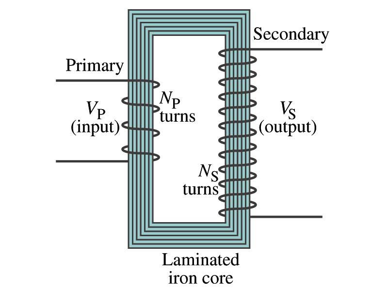
Fig. 3.1 Basic transformer
How do transformers work?
– A changing current through a coil of wire can create a changing magnetic field.
– Currents can be induced in other wires by these changing magnetic field.
– Therefore, the primary coil current must have AC.
– The iron core of the transformer is not required but it does increases the efficiency a great deal.
Theory of the transformer
The operation of a transformer is based on two principles:
A voltage is induced in a conductor when the conductor passes through a magnetic field. The same effect is produced if the conductor is stationary but the magnetic field in which it is located varies; and
A current passing through a conductor will develop a magnetic field around the conductor.
Note: In this discussion on transformers, the term magnetic "flux" will usually be used instead of magnetic "field".
A magnetic field is the space or region surrounding a magnet or a current carrying conductor, in which magnetic effects can be detected.
The strength of the magnetic field is generally expressed in terms of magnetic flux density (magnetic flux per square meter). Magnetic flux refers to the magnetic lines of force.
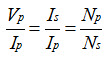
Transformer equation
The transformer equation does not work for Direct current since there is no change of magnetic flux
If NS>NP, the output voltage is greater than the input so it is called a step- up transformer while NS<NP is called step-down transformer
Now, it looks like energy conservation is violated since we can get more emf from smaller ones, right?
– Wrong! Wrong! Wrong! Energy is always conserved!
– A well designed transformer can be more than 99% efficient
– The power output is the same as the input.
![]()
Transformer Equation
When an AC voltage is applied to the primary, the changing B it produces will induce voltage of the same frequency in the secondary wire
So how would we make the voltage different?
– By varying the number of loops in each coil
– From Faraday’s law, the induced emf in the secondary is
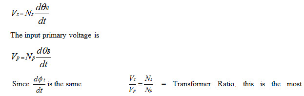
important relationship by which most of the transformer variables are governed and it is denoted (a)
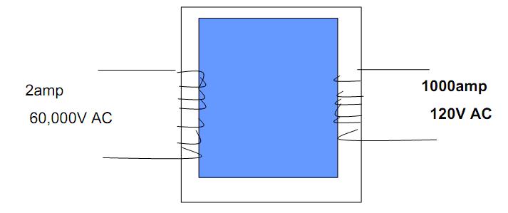
Fig. 3.2 Induction and the transformer
Remember that the relative number of turns dictates the output current and voltage as seen above and by transformer equations.
Last modified: Tuesday, 1 October 2013, 7:06 AM