Site pages
Current course
Participants
General
MODULE 1. Electro motive force, reluctance, laws o...
MODULE 2. Hysteresis and eddy current losses
MODULE 3. Transformer: principle of working, const...
MODULE 4. EMF equation, phase diagram on load, lea...
MODULE 5. Power and energy efficiency, open circui...
MODULE 6. Operation and performance of DC machine ...
MODULE 7. EMF and torque equations, armature react...
MODULE 8. DC motor characteristics, starting of sh...
MODULE 9. Polyphase systems, generation - three ph...
MODULE 10. Polyphase induction motor: construction...
LESSON 6. Construction of single phase transformer
Transformers types
Transformers are manufactured in many types the most widely used in power systems are classified with their core types as seen below. Core type (Fig. 3.3 A) where each of the windings are wound on one leg of the core, while the shell core type (Fig. 3.3 B), in which both windings are wound on the same leg. Each type has its own advantages and disadvantages. Core type is very reliable and easy to maintain, but take larger space, however, shell type is smaller but not reliable.
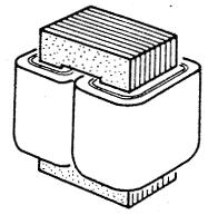
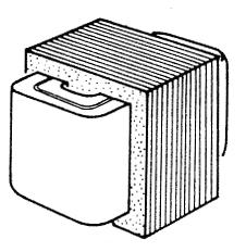
A) Core type B) Shell type
Figure 3.3 Single phase transformer construction
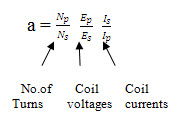
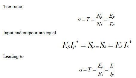
Ideal Transformer:
This is the most known relationships that relates the induction between the two coils (primary/Secondary) of an ideal transformer to turns ratio and their currents
Ideal Unloaded Transformers
-
Winding resistances are zero, no leakage inductance and iron loss
-
Magnetization current generates a flux that induces voltage in both windings
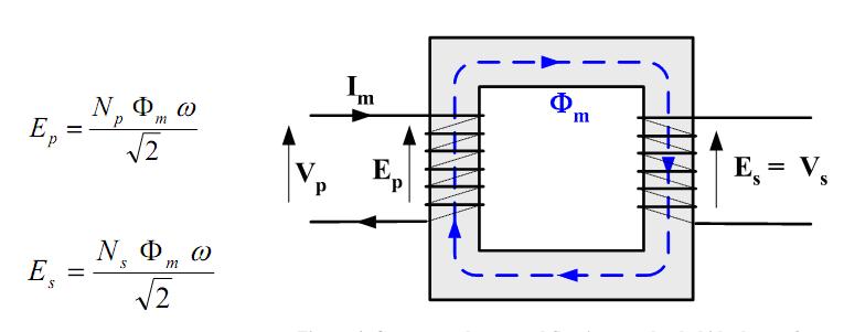
Fig. 3.4 Current, voltages and flux in an unloaded ideal transformer
Ideal loaded transformer
-
Loaded transformer , means current will be also feeding the load and that secondary side voltage, current (load Side) will be calculated using the previous relations
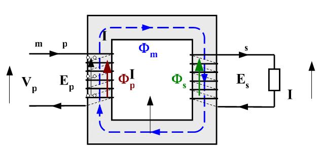
Fig. 3.5 Currents and fluxes in a loaded ideal transformer
Ideal transformers equivalent circuit
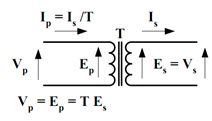
Fig. 3.6 Equivalent circuit of an ideal transformer
Transferring impedances through a transformer
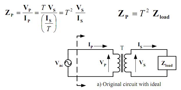
Fig. 3.7 Thevenin equivalent of transformer circuit
Transferring impedances through a transformer
To transfer impedances of either side then the square of the turns ratio is used. 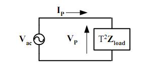
Fig. 3.8 Equivalent circuit when secondary impedance is transferred to primary side and ideal transformer eliminated
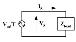
Fig. 3.9 Equivalent circuit when primary source is transferred to secondary side and ideal transformer eliminated
Example: A 200 kV A, 6600 V/400 V, 50 Hz single-phase transformer has 80 turns on the secondary. Calculate:
(i) the appropriate values of the primary and secondary currents;
(ii) the approximate number of primary turns

6600/400 (80)= 1220 turns
Transformer rating = Primary Voltage x Primary current
= Secondary Voltage x Secondary Current
For Primary 200 KVA = (6600) (I1)
I1 = 200KVA/6600v = 30.3 A
For Secondary 200 KVA= 400 I2
I2 = 200 KVA/400v = 500 A
A single-phase transformer has 1000 turns on the primary and 200 turns on the secondary. The no-load current is 3 A at a power factor of 0.2 lagging.
Calculate the primary current and power factor when the secondary current is 280 A at a power factor of 0.8 lagging. Assume the voltage drop in the windings to be negligible.
Answer: 58.3 A, 0.78 pf lagging.
Adapted from EE360 course on Electric Energy Engineering, KFUPM Open Courseware
Last modified: Tuesday, 1 October 2013, 7:07 AM