Site pages
Current course
Participants
General
MODULE 1. Electro motive force, reluctance, laws o...
MODULE 2. Hysteresis and eddy current losses
MODULE 3. Transformer: principle of working, const...
MODULE 4. EMF equation, phase diagram on load, lea...
MODULE 5. Power and energy efficiency, open circui...
MODULE 6. Operation and performance of DC machine ...
MODULE 7. EMF and torque equations, armature react...
MODULE 8. DC motor characteristics, starting of sh...
MODULE 9. Polyphase systems, generation - three ph...
MODULE 10. Polyphase induction motor: construction...
LESSON 12. EMF and torque equations of DC machines
Electromotive Force in an Armature.
The path of the magnetic flux from the poles of a generator into the armature, and a curve showing the flux distribution are shown in figure 7.1. The ordinate at each point is proportional to the flux density in the air-gap at that point. The maximum flux density is given by the ordinate Bmax. The positive ordinates of the distribution curve are north pole flux entering the armature and the negative ordinates are flux leaving the armature and entering a south pole.
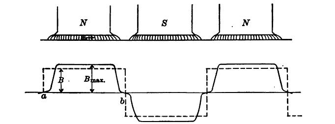
Fig. 7. 1 Flux distribution at no load of a D. C. generator.
The total flux leaving a north pole is given by the area under one of the positive parts of the distribution curve. Similarly, the total flux leaving the armature is the area of one of the negative parts of the distribution curve. Each positive part and each negative part of the curve may be replaced by a rectangle having the same area. The height of this rectangle will be B maxwells / cm2, which is equal to the average value of the flux density under an entire pole pitch.
Now to determine the average electromotive force induced in a single conductor as it passes through the flux of successive poles. Let the total flux leaving a north pole or entering a south pole be φ maxwells. Let A be the pole area in cm2, l the active length of the conductor in cm., s the speed of the armature in revolutions per second, and P the number of poles. When the conductor passes through the distance ab, or one pole pitch, the average induced voltage, by equation studied earlier is
e = Blv 10-8
where, B is the average flux density, I the active length of the conductor in cm., and v the velocity of the conductor in cm. per second.
Then v = ab/t, where ‘t’ is the time required for the conductor to traverse ab.
Therfore, e = Bl (ab/t) 10-8 = (φ/t) 10-8
since Bl (ab) gives the total flux between the points a and b as cut by the conductor and is therefore equal to φ.
The time t = 1/sP
Therefore, the average voltage per conductor is e = (φsP) 10-8
If there are Z such conductors and p paths through the armature, there must be Z / p such conductors in series. Hence the total voltage generated between brushes is
E = (φsPZ) / (p108)
Example.—A 900 r.p.m., 6-pole generator has a simplex lap winding. There are 300 conductors on the armature. The poles are 10 cm2 and the average flux density is 50,000 lines per cm2. What is the voltage induced between brushes?
φ = 10 × 10 × 50,000 = 5,000,000 lines
s = 900/60 = 15 r.p.s ; P = 6; p = 6
E = 5,000,000 ×15 × 6 × 300 / 6 × 10 8 = 225 volts.
The Saturation Curve or No volt characteristic curve:
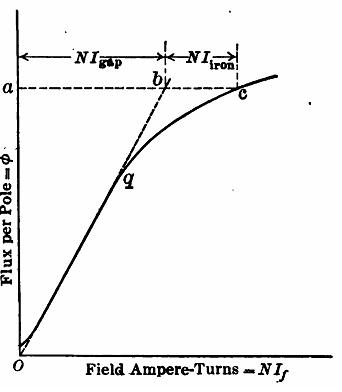
Fig. 7. 2 Saturation curve
The last equation may be written as
![]()
where S = r.p.m.
The quantity within the brackets is constant for a given machine and may be denoted by K. Therefore E = KφS. i.e. the induced emf. in a machine is directly proportional to the flux and to the speed. If the speed is kept constant, the induced voltage is directly proportional to the flux, φ.
The flux is produced by the field ampere-turns, and as the turns on the field remain constant, the flux is a function of the field current. It is not directly proportional to the field current because of the varying permeability of the magnetic circuit.
Figure 7.2 shows the relation existing between the field ampere-turns and the flux per pole. The flux does not start at zero ordinarily but at some value slightly greater, owing to the residual magnetism in the machine. At first the line is practically straight, as most of the reluctance of the magnetic circuit is in the air-gap. At the point ‘q’, the iron begins to be saturated arid the curve falls away from the straight line.
The number of field ampere-turns for the air-gap and for the iron can be approximately determined for any point on the curve.
Let it be required to determine the ampere-turns for the gap and for the iron at the point c. From the origin draw ob tangent to the saturation curve and also draw the horizontal line ac. The line ob is the magnetization curve of the air gap, if the reluctance of the iron at low saturation be neglected. Therefore, the ampere-turns required by the gap are equal to ab and those required by the iron are equal to bc.
The induced voltage is proportional to the flux, if the speed is maintained constant. Two curves as shown in Fig. 7. 3 below can so be plotted for 1,200 r.p.m. and the other for 900 r.p.m. The curves are similar, any ordinate of the lower curve being 900/1,200 of the value of the corresponding ordinate of the upper curve. Thus, at ordinate ‘ac’
ab/ac = 900/1200 Also at a’b’/a’c’ = 900/1200
If the saturation curve of a generator for one speed is available, saturation curves for other speeds may be readily found by the method.
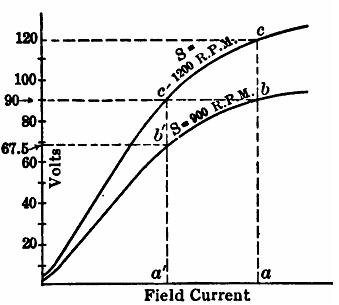
Fig. 7. 3 Saturation curves different speeds.
Determination of saturation curve.
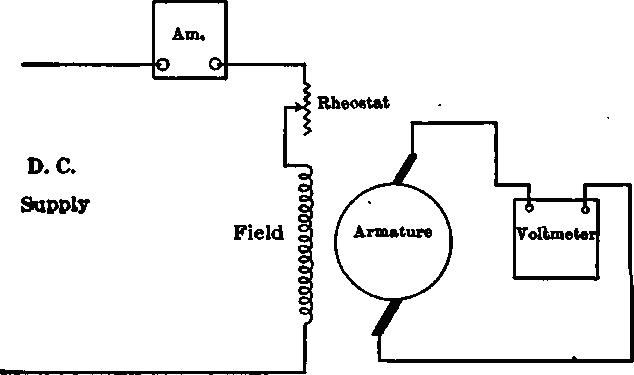
To determine, the saturation curve experimentally, connect the field, in series with an ammeter, across a direct source of power. A voltmeter is connected across the armature terminals under no load. The readings of voltage for each field current is plotted as the saturation curve. As the voltage drop within the armature due to no load current is negligible, the terminal volts and the induced volts under these conditions are identical.
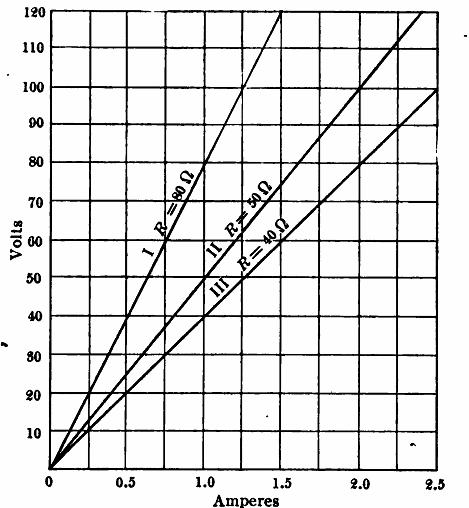
Fig. 7. 4 Field resistance lines.
Field Resistance Line: If the current in a resistance be plotted against volts, a straight line passing through the origin results. For example, if the resistance of a field circuit be 50 ohms, the current will be 2 amperes when the voltage is 100 volts; 1.5 amperes when the voltage is 75 volts, and 1 ampere when the voltage is 50 volts. This relation is shown in the Fig.7.4 below for some values of resistances. It may be noted that the higher the resistance the greater the slope of the resistance line. The slope of the line is equal to the field resistance in ohms.
Last modified: Tuesday, 1 October 2013, 7:12 AM