Site pages
Current course
Participants
General
MODULE 1. Electro motive force, reluctance, laws o...
MODULE 2. Hysteresis and eddy current losses
MODULE 3. Transformer: principle of working, const...
MODULE 4. EMF equation, phase diagram on load, lea...
MODULE 5. Power and energy efficiency, open circui...
MODULE 6. Operation and performance of DC machine ...
MODULE 7. EMF and torque equations, armature react...
MODULE 8. DC motor characteristics, starting of sh...
MODULE 9. Polyphase systems, generation - three ph...
MODULE 10. Polyphase induction motor: construction...
LESSON 14. Shunt generator
The shunt generator
i) Characteristics: If a shunt generator, after building up to voltage, be loaded, the terminal voltage will drop (Fig. 7.10). This drop in voltage will increase with increase of load. Such a drop in terminal voltage is undesirable, especially when it occurs in generators which supply power to lamps. It is very important to know the voltage at the terminals of a generator for each value of current that it delivers, because the ability to maintain its voltage under load conditions determines in a large measure the suitability of a generator for certain specified service.
To test a generator, rated load should first be applied and the field current adjusted until rated voltage is obtained.
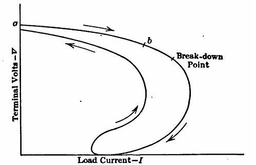
Fig. 7.10 Load Current—/Shunt generator characteristic.
The load should then be cut off and the no-load volts read on the voltmeter. The load should then be gradually applied, reading the volts and the current for each load. The speed of the generator should be maintained constant throughout. If the readings be plotted as shown, the shunt characteristic results. If in a small generator, the load be carried far enough, a rapid decrease of voltage will occur. This is called the break-down point of the generator. Further application of load results in a very rapid decrease of voltage and beyond a certain point any attempt at increase of load results in a decrease of current rather than an increase. The load may even be carried to short-circuit conditions and yet the current will actually decrease as short-circuit is approached. This is due to the fact that the field is short-circuited and any low current flowing at short-circuit is due to the residual magnetism of the machine only.
If the external resistance be now increased, the voltage will rise slowly and will ultimately reach a value that at which it started. The fact that the voltage follows a different curve when the short-circuit is removed is primarily due to hysteresis. When the load is being applied, the voltage is dropping and the iron is on the part of the cycle represented by c. When the voltage starts to increase, it returns along the path a,
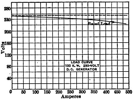
Fig. 7.11 Typical shunt characteristic.
There is less flux for a given field current and consequently less voltage is induced in the machine upon the return curve. This, together with a lesser field current resulting from the lower voltage, accounts for the return curve lying below the other.
In practice, machines are operated only on the portion ab of the characteristic. Figure 7.11 shows the typical curve for a 100-KW., 230-volt generator. The rated current is 100,000/230 = 435 amperes. The generator field rheostat is set so that the generator terminal voltage is 230 volts when it is delivering this load of 435 amperes.
There are three reasons for the drop in voltage (Fig. 7.12) under load of a shunt generator:
(1) The terminal voltage is less than the induced voltage by the resistance drop in the armature. That is, the terminal voltage
V = E - IaRc
where E is the induced volts, J« the armature current and Ra the armature resistance.
(2) Armature reaction weakens the field and so reduces the induced voltage.
(3) The drop in terminal voltage due to (1) and (2) results in a decreased field current. This in turn results in a lesser induced voltage.
Example.— The voltage induced within the armature of a shunt generator is 600 volts. The armature resistance is 0.1 ohm. What is the terminal voltage when the machine delivers 200 amp?
Applying equation, V - 600 - (200 X 0.1) « 600 - 20 - 680 volts
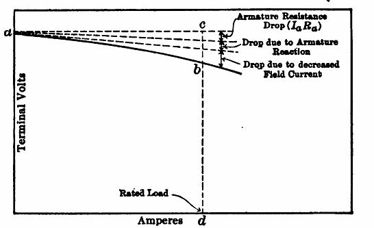
Fig. 7.12 Effect of each of these three factors.
Generator Regulation
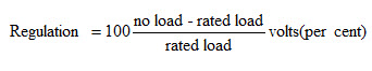
The ability of a generator to maintain its voltage under load is a measure of its suitability for constant potential service. The regulation shows quantitatively the amount the voltage varies from rated load to no load.
The definition of regulation is the rise in voltage between rated load and no load. This is usually expressed as a percentage. Regulation may be more specifically defined as follows:
Total Characteristic: The shunt characteristic is the relation existing between load current and terminal volts (Fig. 7.13). The total characteristic is the relation between armature current and induced volts. The armature current differs from the load current by the amount of current flowing in the field.
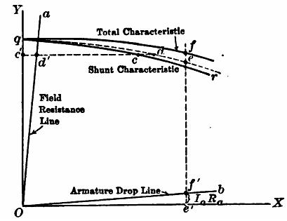
Fig. 7.13 Total characteristic of shunt generator
The armature current,
Ia = I + If
when I is the load current and If the shunt field current. The induced volts
E = V + IaRa
Where, V is the terminal voltage and Ra the armature resistance, including brush and brush contact resistance. The total characteristic is the curve showing the relation of Ia and E. It may be found graphically from the shunt characteristic as follows:
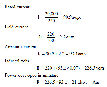
Example.—A 20-KW, 220-volt, shunt generator has an armature resistance of 0.07 ohm and a shunt afield resistance of 100 ohms. What power is developed in the armature when it delivers its rated output?
Last modified: Tuesday, 1 October 2013, 7:14 AM