Site pages
Current course
Participants
General
MODULE 1. Overview of renewable energy sources
MODULE 2. Characterization of Biomass
MODULE 3. Thermochemical conversion Technology (TCCT)
MODULE 4. Biochemical conversion Technology-Biogas...
MODULE 5. Bio-fuels (BCCT)
MODULE 6. Solar Energy Conversion System (SECS)
MODULE 7. Hydro-Energy Conversion System (HECS)
MODULE 8. Wind Energy Conversion System (WECS)
MODULE 9. Ocean Energy Conversion System (OECS)
MODULE 10. Energy conservation in agriculture
LESSON 28. wind mill- aero generator
Basic technology
Wind electric generator converts kinetic energy available in wind to electrical energy by using rotor, gear box and generator.
Wind Power
The terms "wind energy" or "wind power" describe the process by which the wind is used to generate mechanical power or electricity. Wind turbines convert the kinetic energy in the wind into mechanical power. This mechanical power can be used for specific tasks (such as grinding grain or pumping water) or a generator can convert this mechanical power into electricity to power homes, businesses, schools, and the like.
The seasonal as well as instantaneous changes in winds both with regard to magnitude and direction need to be well understood to make the best use of them in windmill designs. Winds are known to fluctuate by a factor of 2 or more within seconds (and thus causing the power to fluctuate by a factor of 8 or more). This calls for a proper recording and analysis of the wind characteristics.
There are various ways the data on wind behavior is collected depending on the use it is intended to be put into. The hourly mean wind velocity as collected by the meteorological observations is the basic data used in a windmill designs. The hourly mean is the one averaged over a particular hour of the day, over the day, month, year and years. The factors, which affect the nature of the wind close to the surface of the earth, they are:
Latitude of the place,
Altitude of the place,
Topography of the place,
Scale of the hours, month or year.
Winds being an unsteady phenomenon, the scale of the periods considered is an important set of data required in the design. The hourly mean velocity (for many years) provides the data for establishing the potential of the place for tapping the wind energy. The scale of the month is useful to indicate whether it is going to be useful during particular periods of the year and what storage if necessary is to be provided for. The data based on scale of the hour is useful for mechanical aspects of design.
Since the winds near the surface of the earth are derived from large scale movement of atmospheric winds, the location height above ground level at which the wind is measured and the nature of the surface on earth have an influence on the velocity of wind at any given time. The winds near the surface of the earth are interpreted in terms of boundary layer concept, keeping in mind the factors that influence its development. The wind velocity at a given height can be represented in terms of gradient height and velocity.
The values of Vg, hg and n depends on the nature of the terrain, which are classified as
Open terrain with few obstacles (open land, lake, shores, deserts, prairies, etc).
Terrain with uniformly covered obstacles (wood lands, small towns, suburbs, etc.)
Terrain with large and irregular objects (large city centres, country with breaks of large trees etc.).
Components of wind electric generator
Basic components of a Wind Electric Systems are,
-
Tower
-
Nacelle
-
Rotor
-
Gearbox
-
Generator
-
Braking System
-
Yaw System
-
Controllers
-
Sensors
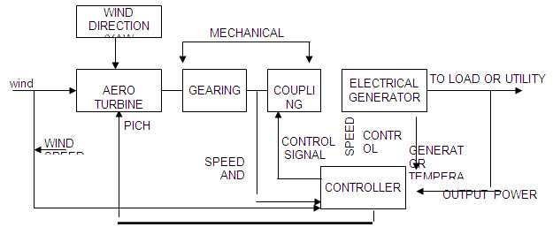
The main components of a WECS are showing in Fig 1 in block diagram form. Summery of the system operation is as follows:
Aero turbines convert energy in moving air to rotary mechanical energy. In general, they require pitch control and yaw control (only in the case of horizontal or wind axis machines) for proper operation. A mechanical interface consisting of a step up gear and a suitable coupling transmits the rotary mechanical energy to an electrical generator. The output of this generator is connected to the load or power grid as the application warrants.
Yaw control. For localities with the prevailing wind in one direction, the design of a turbine can be greatly simplified. The rotor can be in a fixed orientation with the swept area perpendicular to the predominant wind direction. Such a machine is said to be yaw fixed. Most wind turbines, however, are yaw active, that is to say, as the wind direction changes, a motor rotates the turbine slowly about the vertical (or yaw) axis so as to face the blades into the wind. The area of the wind stream swept by the wind rotor is then a maximum.
In the small turbines, yaw action is controlled by tail vane, similar to that in a typical pumping windmill. In larger machines, a servomechanism operated by a wind-direction sensor controls the yaw motor that keeps the turbine properly oriented.
The purpose of the controller is to sense wind speed, wind direction, shafts speeds and torques at one or more points, output power and generator temperature as necessary and appropriate control signals for matching the electrical output to the wind energy input and protect the system from extreme conditions brought upon by strong winds electrical faults, and the like.
The physical embodiment for such an agro-generator is shown in a generalized. The sub-components of the windmill are:
-
wind turbine or rotor
-
wind mill head
-
transmission and control and
-
Supporting structure
Such a machine typically is a large impressive structure.
Rotors
i.Horizontal axis rotor and
ii.Vertical axis rotor.
One advantage of vertical-axis machines is that they operate in all wind directions and thus need no yaw adjustment.
The rotor is only one of the important components. For an effective utilization, all the components need to be properly designed and matched with the rest of the components.
Windmill head
The windmill head
It supports the rotor, housing the rotor bearings. It also houses any control mechanism incorporated like changing the pitch of the blades for safety devices and tail vane to orient the rotor to face the wind. Mounting it on the top of the supporting structure on suitable bearings facilitates the latter.
Transmission
Varying the pitch of the rotor blades, conveniently controls the rate of rotation of large wind turbine generator operating at rated capacity or below,, but it is low, about 40 to 50 revolutions per minute (rpm). Because optimum generator output requires much greater rates of rotation, such as 1800 rpm, it is necessary to increase greatly the low rotor rate of turning. Among the transmission options are mechanical systems involving fixed ratio gears, belts, and chains, singly or in combination or hydraulic systems involving fluid pumps and motors. Fixed ratio gears are recommended for top mounted equipment because of their high efficiency, known cost, and minimum system risk. For bottom mounted equipment which requires a right-angle drive, transmission costs might be reduced substantially by using large diameter bearings with ring gears mounted on the hub to serve as a transmission to increase rotor speed to generator speed. Such a combination offers a high degree of design flexibility as well as large potential savings.
Generator
Either constant or variable speed generators are a possibility, but variable speed units are expensive and/or unproved. Among the constant speed generator candidates for use are synchronous induction and permanent magnet types. The generator of choice is the synchronous unit for large aero generator systems because it is very versatile and has an extensive database. Other electrical components and systems are, however, under development.
Controls
The modern large wind turbine generator requires a versatile and reliable control system to perform the following functions:
-
the orientation of the rotor into the wind (azimuth of yaw);
-
start up and cut-in of the equipment;
-
power control of the rotor by varying the pitch of the blades;
-
generator output monitoring - status, data computation, and storage;
-
shutdown and cut out owing to malfunction of very high winds'
-
protection for the generator, the utility accepting the power and the prime mover;
-
auxiliary and /or emergency power; and
-
maintenance mode.
Many combinations are possible in terms of the control system and may involve the following components:
-
Sensor - mechanical, electrical, or pneumatic:
-
Decision elements - relays, logic modules, analog circuits, a microprocessor, a fluidics, units, or a mechanical unit; and
-
Actuators - hydraulic, electric, or pneumatic. A recommended combination of electronic transducers feeding into a micro-processor which, in turn, signals electrical actuators and provides protection through electronic circuits, although a pneumatic slip clutch may be required.
Towers.
Four types of supporting towers deserve consideration, these are:
the reinforced concrete tower
the pole tower
the built up shell-tube tower, and
the truss tower
Among these, the truss tower is favoured because it is proved and widely adaptable, cost is low, parts are readily available, it is readily transported, cost is low, parts are readily available, it is readily transported, and it is potentially stiff. Shell-tube towers also have attractive features and may prove to be competitive with truss towers.
The type of the supporting structure and its height is related to cost and the transmission system incorporated. It is designed to withstand the wind load during gusts (even if they occur frequently and for very short periods). Horizontal axis wind turbines are mounted on towers so as to be above the level of turbulence and other ground related effects. The minimum tower height for a small WECS is about 10m, and the maximum practical height is estimated to be roughly 60 m.
The turbine may be located either upwind or downwind of the tower. In the upwind location (i.e. the wind encounters the turbine before reaching the tower), the wake of the passing rotor blades causes repeated changes in the wind forces on the tower. As a result, the tower will tend to vibrate and may eventually be damaged. On the other hand, if the turbine is down wind from the tower as shown in figure, the tower vibrations are less but the blades are now subjected to severe alternating forces as they pass through the tower wake.
Both upwind and downwind locations have been used in WEC devices. Downwind rotors are generally preferred especially for the large aero generators. Although other forces acting on the blades of these large machines are significant, tower effects are still important and tower design is an essential aspect of the overall system design.
Water pumping
The sun converts five million tonnes of matter into energy every second. The tiny fraction of energy reaching earth occurs in many farms. One of these is wind energy. Wind energy is extraction of kinetic energy from the wind for conversion into a useful type of energy - mechanical or electrical. The use of wind energy is almost as old as recorded history. Windmills along with watermills were among the original prime movers that replaced animal muscle as a source of energy.
Two important aerodynamic principles are utilized in windmill operation, i.e., lift and drag. The wind can rotate the rotor of a wind mill either by lifting (lift) the blades or by simply pushing against it (drag). Practically a wind mill cannot extract all the power in the wind as it depends upon many factors like the density of the air, wind speed, atmospheric pressure, area of the rotor and design of the rotor. To extract and utilize the maximum possible energy, two principles (lift and drag) are well adjusted while designing a wind mill for a specific application.
There are two different types of wind machines
1. Horizontal –axis wind machine where the rotating axis is parallel to the direction of wind flow and parallel to the ground. There are two or more aerodynamic blades mounted on the horizontal shaft. The blade tips can travel at several times the wind speed which results in high efficiency. The blade shape is designed by suing the same aero-dynamic theory as for aircraft. The low-speed horizontal axis wind mills are used mainly for mechanical purposes, like in water pumps.
2. Vertical – axis wind machines are those where the rotating axis is perpendicular to the wind stream and to the ground. The best known vertical-axis rotor is made up of two identical semi cylinders with their axis vertical. This was developed by the Finnish engineer, Savonious (1931), and is being used increasingly for small wind – energy installations. The French engineer, Davieus designed another type of vertical – axis rotor called Davious type wind mill. Flexible metal strips in the shape of a catenary form the rotor blades. For a given wind speed, the unit rotates more rapidly and is more efficient that the savionious rotor. Unfortunately, the Darreieus rotor is not self-starting even in high winds.
Last modified: Thursday, 3 October 2013, 5:16 AM