Site pages
Current course
Participants
General
MODULE 1.
MODULE 2.
MODULE 3.
MODULE 4.
MODULE 5.
MODULE 6.
MODULE 7.
MODULE 8.
MODULE 9.
MODULE 10.
LESSON 14 DESIGN OF SHAFTS
14.1 Introduction
Shaft is a common machine element which is used to transmit rotary motion or torque. It generally has circular cross-section and can be solid or hollow. Shafts are supported on the bearings and transmit torque with the help of gears, belts and pulleys etc. Shafts are generally subjected to bending moment, torsion and axial force or a combination of these three. So the shafts are designed depending upon the combination of loads it is subjected to. Spindle stub and axle are some important types of shaft. Small shaft is called spindle. Shaft integral part of the prime mover is called stub shaft. An axle is a non-rotating member that carries no torque and is used to support rotating wheels, pulleys etc. And therefore is subjected to bending moment only.
14.2 Shaft Materials
Hot-rolled plain carbon steel is the least expensive material used for shafts. These essentially require machining to remove the scales of hot rolling process. Cold rolled plain carbon steel provides better yield strength and endurance strength but the cold working induces residual stresses. Surface is smooth in this case and amount of machining therefore is minimal. It is used for general purpose transmission shafts. When a shaft is to work under severe loading and corrosive conditions and require more strength, alloy steels are used, generally having Ni, Cr, Mo and V as alloying elements. Alloy steels are expensive. Sometimes shafts are heat treated to improve hardness and shock resistance and surface hardening techniques are also used if high wear resistance is the requirement. As the shafts transmitting power are subjected to fatigue loading, therefore higher factor of safety of 3 to 4 is used on the basis of yield strength for static load analysis.
14.3 Design of Shafts
Shafts are designed on the basis of strength or rigidity or both. Design based on strength is to ensure that stress at any location of the shaft does not exceed the material yield stress. Design based on rigidity is to ensure that maximum deflection (because of bending) and maximum twist (due to torsion) of the shaft is within the allowable limits. Rigidity consideration is also very important in some cases for example position of a gear mounted on the shaft will change if the shaft gets deflected and if this value is more than some allowable limit, it may lead to high dynamic loads and noise in the gears.
In designing shafts on the basis of strength, the following cases may be considered:
(a) Shafts subjected to torque
(b) Shafts subjected to bending moment
(c) Shafts subjected to combination of torque and bending moment
(d) Shafts subjected to axial loads in addition to combination of torque and bending moment
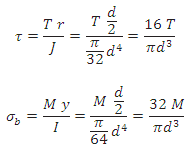
14.3.1 Shafts Subjected to Torque
Maximum shear stress developed in a shaft subjected to torque is given by,
![]()
where T = Twisting moment (or torque) acting upon the shaft,
J = Polar moment of inertia of the shaft about the axis of rotation
= ![]() for solid shafts with diameter d
for solid shafts with diameter d
= ![]() for hollow shafts with do and di as outer and inner diameter.
for hollow shafts with do and di as outer and inner diameter.
r = Distance from neutral axis to the outer most fibre = d/2 (or do/2)
So dimensions of the shaft subjected to torque can be determined from above relation for a known value of allowable shear stress, [τ].
14.3.2 Shafts Subjected to Bending Moment
Maximum bending stress developed in a shaft is given by,
![]()
where M = Bending Moment acting upon the shaft,
I = Moment of inertia of cross-sectional area of the shaft about the axis of rotation
= ![]() for solid shafts with diameter d
for solid shafts with diameter d
= ![]() for hollow shafts with do and di as outer and inner diameter.
for hollow shafts with do and di as outer and inner diameter.
y = Distance from neutral axis to the outer most fibre = d / 2 (or do/2)
So dimensions of the shaft subjected to bending moment can be determined from above relation for a known value of allowable tensile stress, [ ].
14.3.3 Shafts Subjected to Combination of Torque and Bending Moment
When the shaft is subjected to combination of torque and bending moment, principal stresses are calculated and then different theories of failure are used. Bending stress and torsional shear stress can be calculated using the above relations.
Maximum Shear Stress Theory
Maximum shear stress is given by,
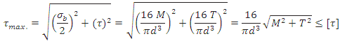
![]() is called equivalent torque, Te, such that
is called equivalent torque, Te, such that
![]()
Maximum Principal Stress Theory
Maximum principal stress is given by,

![]() is called equivalent bending moment, Me, such that
is called equivalent bending moment, Me, such that
![]()
A.S.M.E. Code for Shaft Design
According to A.S.M.E. code, the bending and twisting moment are to be multiplied by factors kb and kt respectively, to account for shock and fatigue in operating condition. Therefore, if the shaft is subjected to dynamic loading, equivalent torque and equivalent bending moment will become:
![]() and
and ![]()
Table 14.1 Values of kb and kt for different types of loading
|
kb |
kt |
||
|
Gradually applied load |
1.5 |
1.0 |
|
|
Suddenly applied load (minor shock) |
1.5-2.0 |
1.0-1.5 |
|
|
Suddenly applied load |
2.0-3.0 |
1
.5-3.0 |
14.3.4 Shafts Subjected to Axial Loads in addition to Combination of Torque and Bending Moment
Tensile Stress due to axial load is given by,
![]()
where, P = axial load acting on the shaft
A = cross-sectional area of the shaft
As nature of the bending stress and this axial stress is same, these can be vectorially added for any location on the shaft, so as to get the resultant tensile/compressive stress, which can then be used to find the principal stresses in the shaft.
14.3.5 Design of Shaft on the basis of Rigidity
14.3.5.1 Torsional Rigidity
For a shaft subjected twisting moment, the angle of twist is given by,
![]()
Where, T = Torqe applied
L = Length of the shaft
J = Polar moment of inertia of the shaft about the axis of rotation
G = Modulus of rigidity of the shaft material
Therefore for the known values of T, L and G and allowable value of angle of twist, diameter of the shaft can be calculated.
15.3.5.2 Lateral Rigidity
Bending moment acting on any shaft is given by,
![]()
Integrating this equation twice with respect to x and applying the boundary conditions, y can be calculated. y should be ≤ allowable value of deflection, [y].
14.3.6 A.S.M.E. Code for Shaft Design
According to A.S.M.E. code, the bending and twisting moment are to be multiplied by factors kb and kt respectively, to account for shock and fatigue in operating condition. Therefore, if the shaft is subjected to dynamic loading, equivalent torque and equivalent bending moment will become:
![]() and
and ![]()
Table 14.1 Values of kb and kt for different types of loading
|
|
kb |
kt |
|
Gradually applied load |
1.5 |
1.0 |
|
Suddenly applied load (minor shock) |
1.5-2.0 |
1.0-1.5 |
|
Suddenly applied load |
2.0-3.0 |
1.5-3.0 |
References:
- Design of Machine Elements by VB Bhandari
- Analysis and Design of Machine Elements by VK Jadon
- A Text Book of Machine Design by RS Khurmi
- Mechanical Engineering Design by JE Shigley
- Design of Machine Elements by K Babu
Last modified: Thursday, 20 March 2014, 7:26 AM