Site pages
Current course
Participants
General
MODULE 1.
MODULE 2.
MODULE 3.
MODULE 4.
MODULE 5.
MODULE 6.
MODULE 7.
MODULE 8.
MODULE 9.
MODULE 10.
LESSON 16 DESIGN OF COUPLINGS
16.1 Introduction
Couplings are used to connect two rotating shafts to transmit torque from one to the other. For example coupling is used to connect the output shaft of an electric motor to the input shaft of a hydraulic pump.
16.2 Types of Shafts Couplings
Rigid Couplings
Rigid Couplings are used to connect two shafts which are perfectly aligned. These are simple and inexpensive.
Rigid Couplings are of following types:
- Sleeve or Muff Coupling
- Clamp or Split-muff or Compression Coupling
- Flange Coupling
Flexible Couplings
Flexible couplings are used to connect two shafts having lateral or angular misalignment. Flexible elements provided in flexible coupling absorb shocks and vibrations.
Flexible Couplings are of following types:
- Bushed pin type Coupling
- Universal Coupling
- Oldham Coupling
16.3 Muff Coupling
16.3.1 Introduction
Assembly of muff coupling is shown in Figure 16.1. Sleeve, a hollow cylinder, is fitted on the ends of input and output shaft with the help of a sunk key. Torque is transmitted from input shaft to the sleeve through key and from the sleeve to the output shaft through the key again. It is simple to design and manufacture but difficult to assemble and dismantle. It requires more axial space and has small radial dimensions. Sleeve is made of cast iron and for it a larger factor of safety of 6-8 is used on the ultimate strength. Standard proportions used for sleeve are:
Outer diameter of the sleeve, D = 2d + 13
Length of the sleeve, L = 3.5d
where d is the diameter of the shaft.
So the muff coupling has three main components: shafts, sleeve and key.

Figure 16.1 Muff Coupling
16.3.2 Design
16.3.2.1 Design of Shafts
Shafts are designed on the basis of torsional shear stress induced because of the torque to be transmitted. Shear stress induced in shaft for transmitting torque, T is given by,
![]()
Where T = Twisting moment (or torque) acting upon the shaft,
J = Polar moment of inertia of the shaft about the axis of rotation
r = Distance from neutral axis to the outer most fibre = d/2
So dimensions of the shaft can be determined from above relation for a known value of allowable shear stress, [τ].
16.3.2.2 Sleeve Design
As discussed earlier, following relations are used to calculate the dimensions.
D = 2d + 13 L = 3.5d
Then the torsional shear stress in the sleeve is checked considering it as a hollow shaft.
Shear stress, ![]()
where, T = Twisting moment (or torque) to be transmitted
J = Polar moment of inertia about the axis of rotation
r = Distance from neutral axis to the outer most fibre = D/2
16.3.2.3 Design of Key
Cross-section of the key is taken from the table corresponding to the shaft diameter or relations (square key) or and (for rectangular key) are used to find the cross-section, where w is width and h is the height of the key.
Length of key in each shaft, .
The keys are then checked in shear and crushing.
|
Shear stress, |
|
|
Crushing stress, |
|
16.4 Clamp Coupling
16.4.1 Introduction
Clamp coupling is also known as split-muff coupling or compression coupling. In this coupling, sleeve or muff is made in two halves, which are split along the plane passing through the axes of the shafts. These two halves are clamped together with the help of bolts, which are placed in recesses made in the sleeve halves. Dynamic balancing of clamp coupling is difficult making it unsuitable for high speed applications. It is also unsuitable for shock loads. Assembly and dismantling is easier for this coupling. Figure 16.2 shows Clamp Coupling assembly.
A small clearance is provided between the two halves of the sleeve along the parting line and the force due to clamping of bolts creates frictional force between the surface of the shafts and inner surface of sleeve halves. Torque is transmitted by means of this frictional force and through the key, from the input shaft to the sleeve and from sleeve to the output shaft. It is not possible to find out the exact percentage of torque transmitted by friction and by the key. Therefore, for designing the bolts it is assumed that whole of the torque is transmitted by friction and while designing the key, it is assumed that whole of the torque is transmitted by it.
Design is similar to the design of muff coupling and an additional calculation is required for designing the bolts.

Figure 16.2 Clamp Coupling
16.4.2 Design
Design of Clamp Coupling is similar to the design of muff coupling and an additional calculation is required for designing the bolts.
16.4.2.1 Design of Shafts
Same as discussed in sleeve coupling.
16.4.2.2 Sleeve Design
Same as discussed in Sleeve Coupling
16.4.2.3 Design of Key
Same as discussed in Sleeve Coupling
16.4.2.4 Design of Bolts
Bolts are designed assuming that whole of the torque is transmitted by friction between sleeve and shafts.
Let [σt] = permissible tensile stress of bolts
dc = core diameter of bolts
n = number of bolts
Clamping force of each bolt,
![]()

Figure 16.3 Forces acting on Bolts
Assuming that half of the bolts apply clamping force on one shaft and half of the bolts on the other. Clamping force on each shaft, ![]()
Frictional Torque, ![]()
where, m = coefficient of friction between shafts and sleeve.
Above two relations can be used to find the core diameter of the bolts by equating to the total torque transmitted.
16.5 Flange Coupling
16.5.1 Introduction
Flange coupling consists of two flanges keyed to the shafts. The flanges are connected together by means of bolts arranged on a circle concentric to shaft. Power is transmitted from driving shaft to flange on driving shaft through key, from flange on driving shaft to the flange on driven shaft through bolts and then to the driven shaft through key again. Projection is provided on one of the flanges and a corresponding recess is provided in the other for proper alignment. Flange coupling is of two types – unprotected and protected. These are shown in Figure 16.3. If in case failure of bolts occurs during the operation, the bolts may hit the operator in case of unprotected flange coupling. To avoid this, protective circumferential flanges are provided in the protected type flange coupling.
Flange of a protected type flange coupling has three distinct regions – inner hub, flanges and protective circumferential flanges. Following standard proportions are used in the design of flange coupling:
Outer diameter of hub, D = 2 d
Pitch circle diameter of bolts, D1 = 3 d
Outer diameter of flange, D2 = 4 d
Length of the hub, L = 1.5 d
Thickness of flange, tf = 0.5 d
Thickness of protective circumferential flange, tp = 0.25 d
where d is the diameter of shafts to be coupled.

Figure 16.4 Flange Coupling
16.5.2 Design
16.5.2.1 Design of Shafts
Same as discussed in sleeve coupling.
16.5.2.2 Design of Hub
Hub is designed considering it as a hollow shaft, with inner diameter equal to diameter of shafts and outer diameter double of that. It is checked for torsional shear stress.
Shear stress, ![]()
Where T = Twisting moment (or torque) to be transmitted
J = Polar moment of inertia about the axis of rotation
r = Distance from neutral axis to the outer most fibre = D/2
16.5.2.3 Design of Key
In this case two separate keys are used for the two shafts. Key is designed as discussed earlier. In this case, length of key, (length of the hub)
16.5.2.4 Design of Flange
The flange is subjected to shear at the junction of the hub as it transmits torque through the bolts. Area resisting shear
where, is the thickness of the flange.
|
If T is the torque to be transmitted, tangential force, |
|
|
|
Shear stress, |
|
|
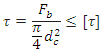
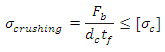
16.5.2.5 Design of Bolts
Due to transmission of torque, force acts perpendicular to the bolt axes and the bolts are subjected to shear and crushing stresses. Let n be the total number of bolts.
|
Force acting on each bolt, |
|
where D1 is the pitch circle diameter of bolts.
|
Area resisting shear |
|
|||
|
where, dc = core diameter of bolts |
|
|||
|
Shear stress, |
|
|||
|
Area under crushing |
|
|||
|
Crushing stress, |
|
|||
References:
- Design of Machine Elements by VB Bhandari
- Analysis and Design of Machine Elements by VK Jadon
- A Text Book of Machine Design by RS Khurmi
Last modified: Thursday, 20 March 2014, 9:20 AM