Site pages
Current course
Participants
General
Module 1. Tractor Mechanics
Module 2. Traction
Module 3. Introduction to Transmission System
Module 4. Clutch System
Module 5. Gear Box
Module 6. Differential and Final drive
Module 7. Brakes
Module 8. Steering system
Module 9. Hydraulics
Module 10. Power Transmission
Module 11. Human Factors
Lesson 26. Hydraulic steering
POWER STEERING
Tractors having 30 KW or more power generally will have power steering. This is based on two basic fluid power types: There are
- Hydromechanical systems
- Full hydraulic systems, commonly called hydrostatic power steering
Hydromechanical systems
The term "hydrostatic" means those systems requiring no mechanical linkage between the driver's steering wheel and the steered wheels. In this system fluid under pressure is used not only power the load but also to provide hydraulic feedback from load and to transmit manual effort to the load when the power source is unavailable. The two most important advantages of the hydrostatic system are
- Flexibility of installation
- Lower cost
The most distinguishing feature common to hydrostatic steering systems is the use of a positive displacement flow metering or measuring device coupled to the steering wheel shaft. Hydrostatic systems can be categorized by the manner in which this metering device operates in the control loop. At least four basic types can be identified as given below:-
TYPE-1
The metering unit is mechanically linked to steering shaft and control value and is hydraulically connected in series to the actuator. It provides the remote monitoring of actuator position at the control value location, known as position feedback. an input error between the steering shaft and the metering unit is measured and translated into control value displacement by suitable mechanical means. The subsequent response of the actuator - metering unit to the directed flow cancels the error, thus returning the control value to the null position.
Type-2
The metering unit is rigidly coupled to the steering shaft and hydraulically connected in series with actuator, but in parallel with the control value pilot chambers. Here the metering unit functions as a transducer to convert steering wheel rotation and input torque into flow and pressure to displace the control value. The resulting flow of high pressure oil again passes through the metering unit before entering the actuator. The incremental activator motion, which continues after the steering wheel stops, hydraulically recenters the control value.
TYPE-3
The metering unit is mechanically linked to the steering shaft and control value as in type 1 but is hydraulically connected to a separate feedback displacement device, which in turn is linked to the output motion. This permits the control circuit to be isolated from the power circuit.
TYPE-4
The metering unit is rigidly attached to the steering shaft and hydraulically connected to the control value as in Type 2, but it is hydraulically coupled to a separate feedback device as in type 3. This is a simpler, lower cost arrangement than type 3 but introduces an operational factor.
Parameters that influence power requirements are:
- Tire loading
- Road surface and soil conditions
- Tire inflation pressure
- Tire sizes and tread patterns
- King-pin inclination
- Caster angle
- Camber angle
- King-pin offset
- Toe-in and toe-out
- Tread setting
- Travel speed
- Steering rates
- System efficiency
- Front end type
- Tractive and braking force
- Chassis type
Heaviest steering loads with Ackerman-type steering usually occur with a stationary tractor on dry and clean concrets. This condition provides a convenient standard for calculating maximum power requirements.
On Ackerman - type tractors, tire loading is the most significant variables affecting power requirements. Tire load ranges from minimum needed for longitudinal stability to a maximum usually dictated by tire load rating. If excessive steering force is provided, tires may be twisted from the rims or structural damage inflicted on linkage or chassis members if the tires become lodged. To avoid this possibility, it has been recommended that power steering forces be limited to about 110% of the maximum design condition.
ACTUATORS FOR POWER STEERING
The location of the actuator in the linkage will determine the mechanical efficiency between the output member and the tire print. Overall efficiencies of manual steering gears and their associated linkage are generally in the range of 40-70% depending upon the types of antifriction means employed. typical efficiencies for actuators usually fall between 80-90% with the cylinder types being some what higher than the rotary rack and pinion or vane types (Fig. below).
Actuator output travel (stroke or angular rotation) is governed to some extent by steering geometry limitations; however, it has been recommended that a stroke bore ratio for cylinders between S and 8 be selected, if possible, to maintain adequate column strength and a favourable servo-value amplification to linkage diflection relationship.
If the steering is to be powered from the pressure, a desired load pressure can be chosen from the following equation.
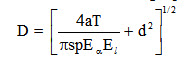
Where,
D = piston diameter, mm
a = lock-to-lock steering angle, radius
T = required king-pin torque, N-mm
S = piston stroke, mm
p = effective pressure at piston face, MPa
Ea = overall actuator efficiency
El = linkage efficiency
d = piston rod diameter, mm
In terms of displacement, the equation becomes:

Where,
v = acuator displacement, mm3
The appropriate multipliers must be applied to accommodate multiple actuators and/or number of torque loads involved. If the effects of king-pin inclination, cater and camber are significant, a modified value of aT should be determined and substituated. The effect of caster and camber are usually small. However, large king-pin inclination angles produce a significant lifting actin to the axle which adds to the king-pin torque when going into a turn.
It will be noticed that the energy required for steering an articulated frame, tractor is about 3.5 times that for an Ackerman-steer type tractor with the same axle load. These values will normally provide acceptable performance for all but stationary steering under maximum load condition.
POWER STEERING PUMP
The power source for a steering system can be either a separate pump, the central hydraulic system ump or a combination of both. High quality, fixed clearance gear or vane pumps are used for pressures upto 10.3 MPa. The majority of open centre steering pumps, both on farm tractors and on trucks and automobiles are of this type.
Most commercial power steering pumps are designed to be belt or gear driven and have speed capabilities above the engine speed typical on farm tractors. Unless the pump is to be driven directly off the crank shaft the higher permissible speeds should be exploited to reduce size and cost. Common maximum pump speeds are from 3000-5000 rpm. The required pump flow is given by
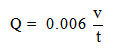
Where,
Q = pump flow rate, lit/min
v = actuator total displacement volume, cm3
t = desired steering time from lock-to-lock turn, s
A steering wheel rate of less than one revolution per second is seldom satisfactory and more than twice is rarely desired. A steering time t of 2-4s, lock-to-lock is typical.
With flow rate, Q, and time, t, the pump displacement can be computed.
The power requirement of the pump is
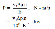
Where
Δp = pressure rise through pump, Pa
E = overall pump efficiency
n = revolutions/s
v1 = displacement volume, cm3
Last modified: Monday, 3 March 2014, 6:43 AM