Site pages
Current course
Participants
General
Module 1. Hydraulic Basics
Module 2. Hydraulic Systems
MODULE 3.
MODULE 4.
MODULE 5.
MODULE 6.
MODULE 7.
MODULE 8.
LESSON 25. Hydraulic motors
Introduction
Hydraulic motors are the devices which receives pressure energy and converts it to mechanical output in the form of motion or rotation. These are rotary actuators. A rotary actuator produces torque and rotating motion is called a hydraulic motor or simply motor. Hydraulic actuators are the muscles of many machines. They are produced in varying sizes from miniature units to massive actuators. A rotary actuator is a device that produces a rotary motion or torque. The motion developed by an actuator may be either continuous rotation or an angular rotation..It basically transforms the hydraulic energy into rotary energy in the form of mechanical rotations which can be applied to an object with the help of a shaft.
Hydraulic Motors
A hydraulic motor is a device which converts the flow of a liquid under pressure into rotational motion. It is similar in construction to a hydraulic pump. Instead of mechanical parts are moved and fluid is pushed , high-pressure fluid pushes the mechanical parts, causing them to move. The rotary motors are provided in the hydraulic systems to convert the fluid power into shaft power by forcing the shaft to rotate .When fluid pushed is at faster speed , the shaft speed is more and vise versa. Basically there are three types of hydraulic motors, like- gear, vane and piston.
Gear Motor
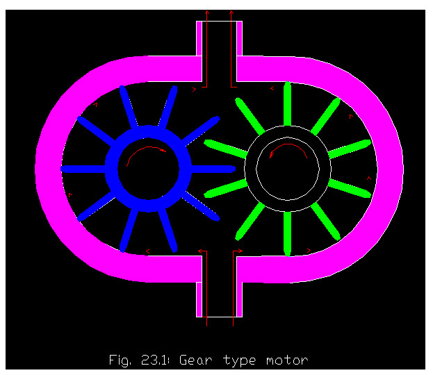
The gear motor is consist of two meshed gears in a housing, with inlet and outlet pipes on opposite sides. Both gears are driven gears, but only one is connected to the output shaft. Its working is reverse of a gear pump. Fluid at high pressure is injected into the housing, where it flows , between the gear teeth and the housing wall. Similar to the gear pump gears in gear motor are closely fitted into the housing. This forces the gears to rotate. The meshing teeth of gears prevent the fluid from flowing back, and results in continuous rotations. This rotary motion is then available in the form of rotary work at the output shaft. The direction of motion can be reversed by changing the direction of fluid through the motor.

Vane Type motor
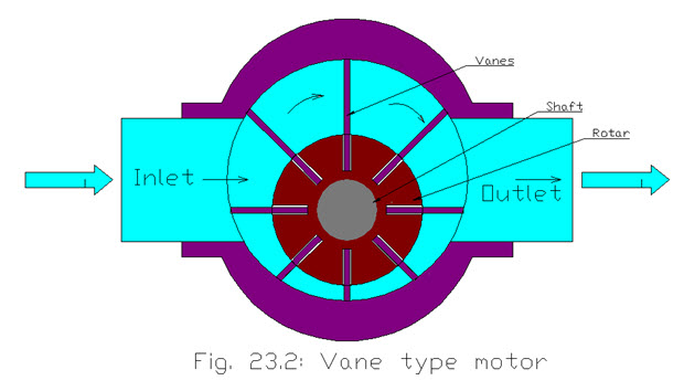
This type of motor is a positive displacement motor. Vane motors is having a single rotor with vanes sticking at the housing wall of motor. The inlet and outlet pipes are located on opposite sides of the motor. The fluid flow from the pump enters the inlet of the motor and forces the rotor and vanes to rotate, and passes out through the outlet pipe. As motor rotate it causes the output shaft to rotate . As the vane is near to inlet pipe, it get rotated due to fluid and a tight seal is created .The seal is loosening and letting the fluid flow from the outlet pipe of the housing of the motor. Since the fluid is always pushing against the vanes tangentially, the rotor is rotated by the fluid pressure.

Piston Motors
This type of motor is a positive displacement motor which can develop torque at shaft with the help of pressure of the fluid. It may be of following three types
In line piston
Axial piston
Radial piston
Axial piston
This type of motor consists of a cylinder fitted with a number of pistons. As the fluid is forced into the cylinder barrel with pressure, the pistons forced outward against an angled plate. By pushing on the plate at an angle, the pistons rotate the plate and generate torque. Y In this manner fluid energy is converted into rotary output .
Radial piston
Radial piston motors are best suited for low speed high torque applications, like in winches. Radial piston motors are designed in in varying capacities ranging from 20 to 10,000 cm3/rev at higher pressures like 450x105N/m2 or so. In radial piston motor the pistons are connected to a shaft with the help of crank . The pump flow into the cylinder forces the piston to reciprocate and rotate the shaft. In this way a high power and torque is produced.
 Points to be considered while choosing a hydraulic motor
Torque needed
Working pressure of the hydraulic system
Speed required
Size of fly wheel required
Heat generated if any
Calculations in Motor
Motor Power
It is the output power of motor shaft which can be defined as the product of shaft torque and speed .
Ps = \[\frac{{2\pi N}}{{60}}\]
where N = speed (rpm)
\[\tau \] = torque
Fluid Power Calculations
It can be defined as the energy per second by the fluid in the form of pressure and the quantity of fluid. It is product of fluid quantity (flow rate) and the differential pressure. Hence
Pf = Q x Δp
Where Pf = Fluid power
Q = flow rate , m3/s
Dp = differential pressure, N/m2
Overall Efficiency
It can be defined as the ratio of output power to the input power or shaft power to the fluid power, which can be given as-
\[\eta \]ova = ![]()
\[\eta \]ova = \[\frac{{{\text{Shaftpower}}}}{{{\text{Fluidpower}}}}x100\]
\[\eta \]ova = \[\frac{{{\text{Ps}}}}{{{\text{Pf}}}}x100\]
Where
\[\eta \]ova = overall efficiency
Pf = Fluid power
Ps = Shaft power
Speed and Flow Rate
The flow rate and speed can be given as-
Flow rate Q = Kq x speed
Where Kq = Nominal displacement of motor, cm3/rev
Torque and Pressure
Let motor be 100% efficient, then the shaft power will be equals to fluid power.
Therefore,
Shaft power = Fluid power
Ps = Pf
\[\frac{{2\pi N}}{{60}}\] = Q x Dp
\[\tau\] = \[\frac{{{\text{Qxpx}}60}}{{2\pi N}}\]
Volumetric Efficiency
It can be defined as the ratio of theoretical flow rate to the actual flow rate of fluid.
Let
Qa = actual flow rate
Qt = theoretical flow rate
\[\eta \]vol = volumetric efficiency
\[\eta \]vol = \[\frac{{{\text{Qt}}}}{{{\text{Qa}}}}\] x 100
Example
A hydraulic motor is running at a speed of 395 rpm with the differential pressure of 8.2x10⁶ N/m2. The nominal displacement is 5 cm3/rev and the overall efficiency and volumetric efficiency of 86 and 89% respectively. Calculate the followings-
a) Theoretical flow rate
b) Actual flow rate
c) Fluid power
d) Shaft power
e) Torque of shaft
Soln.
Given N = 395 rpm
Δp = 8.2x10⁶ N/m2
\[\eta \]ova = 86%
\[\eta \]v = 89%
Kq = 5cm3/rev
= 5x10⁻⁶m3/rev
Theoretical flow rate Qt = KqxN
= 5x10-6x395/60
= 3.29x10⁻⁵ m3/s
\[\eta \]vol = \[\frac{{{\text{Qt}}}}{{{\text{Qa}}}}\] x 100
\[{\text{Qa}}\] = \[\frac{{{\text{Qt}}}}{{\eta {\text{vol}}}}\] x100
= \[\frac{{3.29{\mathbf{x}}10 - 5}}{{89}}\] x100
= 3.69x10⁻⁵ m3/s
Fluid power Pf = Q x Δp
= 3.69x10-5 x 8.2x106
= 303.27 Nm/s
= 303.27 watt
Shaft Power \[\eta \]ova = \[\frac{{{\text{Ps}}}}{{{\text{Pf}}}}x100\]
Ps = \[86x303.27{\text{}}/{\text{}}100\]
= 260.8 watt
Shaft Torque
Ps = \[\frac{{2\pi N}}{{60}}\]
\[\tau \] = \[\frac{{Psx60}}{{2\pi N}}\]
= \[\frac{{260.8x60}}{{2x\pi x395}}\]
= 6.3 Nm