Site pages
Current course
Participants
General
Module 1. Hydraulic Basics
Module 2. Hydraulic Systems
MODULE 3.
MODULE 4.
MODULE 5.
MODULE 6.
MODULE 7.
MODULE 8.
LESSON 26. Valves pressure control valves, Direction control valves, Flow control valves
Introduction
In the hydraulic systems valves play an important role. These are necessary to control the pressure, flow rate and the direction of flow in the circuit. These are generally made with high standards, strong materials and with precision. These valves can be operated manually, hydraulically, pneumatically or electrically. It can be classified as-
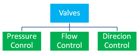
Pressure Control valves
This type of valves are used to control the pressure of hydraulic system or circuit and called pressure control valves. It includes pressure reducing valve, pressure relief vale etc.
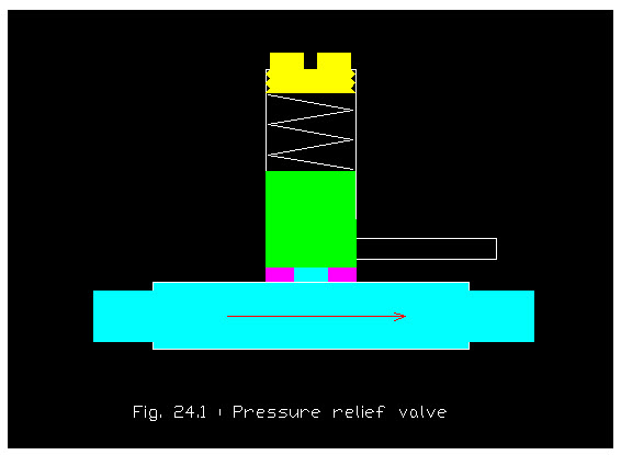
Pressure relief valve
This type of valves are utilized to limit the maximum operating pressure in the circuit. These are also called safety valves and protects the pump and other components from overloading, etc. Pressure relief valve is provided in the circuit such that one port is connected to the pressure line and the other port is connected to the the reservoir. There is a ball which is held on its seat with the spring force. The spring force can be changed by rotating the adjusting screw. When the circuit pressure at the valve inlet is less than the spring pressure , the ball remains on its seat and the valve is closed and no flow takes place through it. As the pressure in the circuit exceeds the adjusted spring force, the ball is forced off its seat and the valve is opened. Now the liquid flows from the pressure line through the valve to the reservoir. This diversion of flow continue till the. pressure decreases below the valve setting and hence the spring reseats the ball and the valve is again closed. In this way it prevents circuit and provide the safety.
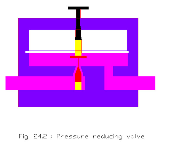
Pressure reducing valve
Pressure reducing valves are used to reduce the output pressure which is part of circuit from rest of circuit . It generally limits the pressure in a branch circuit at lesser value than the required in the main circuit. If in a hydraulic system, a branch circuit is required to be limited to a pressure of 200 N/cm2, but the main circuit is to be operated at a pressure of 600 N/cm2. Therefore, a relief valve in a main circuit will be kept at a pressure setting above 600 N/cm2 to meet the main circuit requirements. Therefore, in the branch circuit a pressure reducing valve will be provided to keep the pressure at 200 N/cm2 It is normally a open valve rather than closed as in relief valve. As the liquid from the main circuit enters the valve at the inlet port it flows and enters the branch circuit through the outlet port .The fluid bleeds to the tank through the valve drain passage, pressure will start reducing . This result in a reduced pressure equal to the setting of the valve.
Flow Control valves
Flow control valves are those which are used to control the flow rate of the fluid in the circuit and also called volume control valves, like needle valve, globe valve, gate valve, etc. Flow-control valves are generally used to control the speed of hydraulic motors or actuators in work spindles and the travel rates of tool heads, etc. Flow control valves keeps uniform flow rate in the circuit with the help of pressure compensator. A non pressure, compensated flow control, like in needle valve etc., there may be changes in the flow rate.
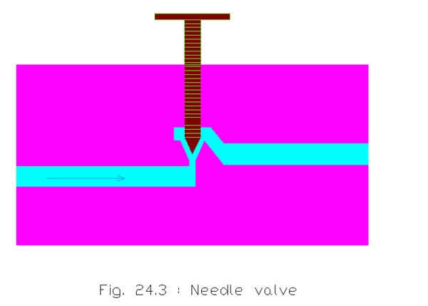
Needle valve
Needle valves are generally designated as non-compensated flow control or throttling valves. They are good metering devices when the pressure differential across the valve remains constant. This type of valve is used in the hydraulic system where there is no need of precise speed control because the flow may vary with pressure difference. A needle valve and globe valve are similar in design and operation . In this type of valve there is a long, tapered point at the end of a valve stem which can be raised or lowered to control the flow through it. A long taper allows a needle valve to open or close gradually. A needle valve is used to control flow at points where a small flow rate is desired or at other points where precise flow is required.
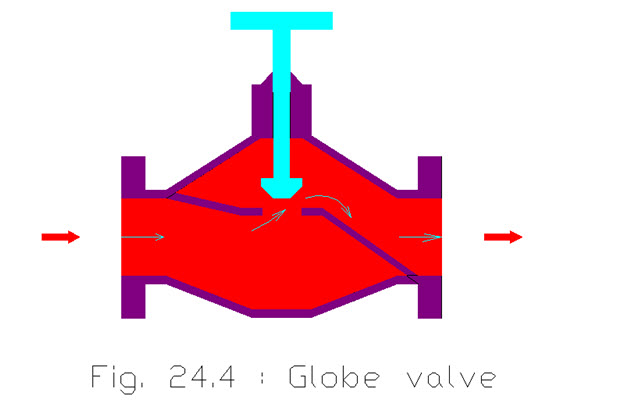
Globe Valve
In the globe valve there is a disc, which is attached to the end of the stem which controls flow of fluid through the valve. The valve is closed by lowering a disc into a valve seat and opened by raising it off the seat. Since fluid flows equally on all sides when a valve is open, there is no unbalanced pressure on a disc to cause uneven wear.
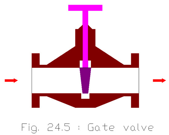
 Gate Valve
This type of valves are normally used to allow or prevent the flow of liquids and also used for regulating the flow of fluid. In this type of valve there is a wedge or sort of gate which controls the flow. Opening and closing of a passage is done with the help of a hand wheel, which moves a wedge or gate up and down across a flow line. The gate valve is provided with good sealing surfaces between the gate and seats. As the valve is opened, the gate moves up within the bonnet and as it is closed, the gate blocks the flow by coming across the line where it rests firmly against the seats. The gate valve permits the flow and offers small or no resistance to the fluid flow when the valve is fully open. But if it is in the partially open it restrict the flow rate through the circuit.
Direction Control valves
Those valves which are use to give a particular direction to the fluid in the circuit are called direction Control valves, like spool valve.
Spool valve
Spool valve is a valve which controls the direction of hydraulic fluid flow. It consists of cylindrical spools which can block and open the channels in the hydraulic system. A spool valve can change the direction of flow of hydraulic fluid from a hydraulic pump to an actuator by blocking off the route of the fluid through which it takes place.
Spool valve is consists of a spool which can move in the body of the valve and may have four or five ports. As in the figure below, a three way spool valve connected to an actuator of cylinder type. The fluid is applied to the port P of the valve and C of the cylinder, whereas, port T of the valve is connected to drain or return to the tank. Port A of the valve is connected to the B of the cylinder. Now if the spool is moved to right side with the help of lever, the high pressure fluid flows from port A and B. The moves to right due to pressre of fluid and displacing the fluid through port C and P.Now if the spool is moved to left, high pressure fluid comes into the cylinder through port C, and the piston moves to left causing the fluid into the tank via port B and A and T.
 Sequence valve
It is also a sort of direction control valve which gives the sequence of operation in the hydraulic circuit. It gives entire fluid to one of the circuit until pump delivery exceeds the requirement
of that particular circuit and then extra fluid is made available to other circuits. This type of valve is very much of use in the machine tool operation. One of the outlet port is open and the and is utilized for clamping of work piece. After completing this operation fluid pressure builts up and forces the spool to move against the spring force and allowing the fluid to flow through port 2 to actuate main actuator for tooling of work piece.
Last modified: Tuesday, 18 March 2014, 7:31 AM