Site pages
Current course
Participants
General
Module 1. Hydraulic Basics
Module 2. Hydraulic Systems
MODULE 3.
MODULE 4.
MODULE 5.
MODULE 6.
MODULE 7.
MODULE 8.
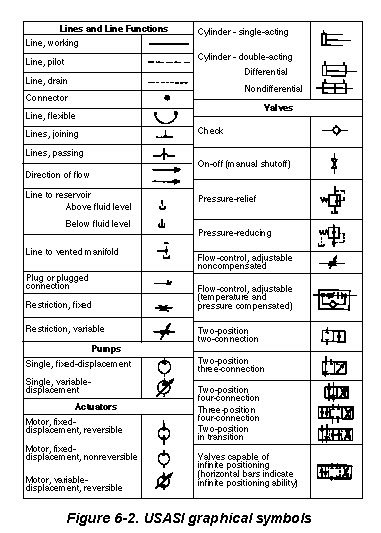
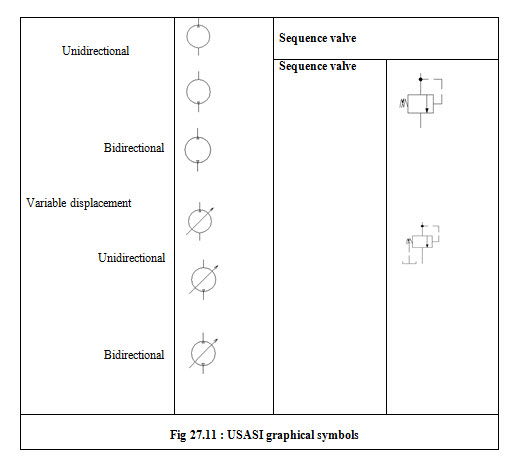
Lesson 29 United States of American Standards institute ( USASI ) Graphical symbols
Introduction
Schematic symbols are used to identify and graphically depict the function of fluid power components. Recognizing and understanding schematic symbols will enable us to know about the circuit functioning. The United States of American Standards Institute (USASI), the old American Standards Association (ASA), and the Joint Industry Conference (JIC) are three systems of symbols used in circuit diagrams.
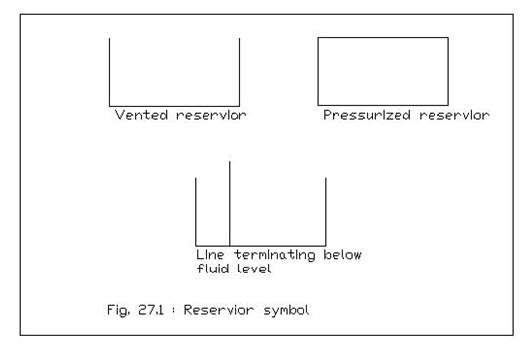
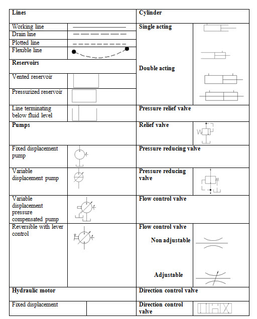
Reservoir
It is represented by a rectangle in which horizontal side is kept longer than the other side. A reservoir if vented to the atmosphere, the top of the symbol is open and a reservoir if pressurized, the top is closed. Lines which connect to a reservoir usually drawn from the top. But the line terminates below the fluid level, it is drawn to the bottom of the symbol.
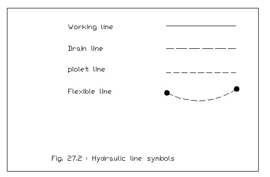
Lines
Working line
It is made as solid line which indicates a hydraulic pipe, tube, hose, or other conductor carrying the fluid between the components.
Pilot line
It is given by long dashes which indicates control lines.
Drain line
It is given by short dashes which indicates drain lines.
Flexible line
It is made a solid, arced line which is drawn between two dots which represents a flexible line in the system.
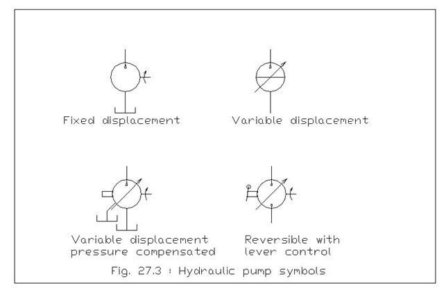
Pump
The hydraulic pump is a usually given by a symbol of circle with a black triangle in the circle pointing outward. The triangle indicates the flow direction The pressure line from the pump is drawn from the tip of the triangle, whereas, the suction line is drawn opposite it.. If a pump is reversible, it will have two triangles.
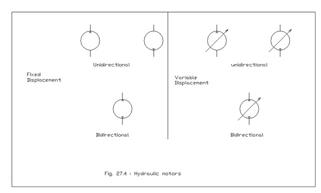
Motor
In the hydraulic system motor is also symbolized as circle like in pump but the black triangles pointing inward, which is a indication of receiving of pressure energy. One triangle indicates a nonreversible motor; two triangles indicate a reversible motor.
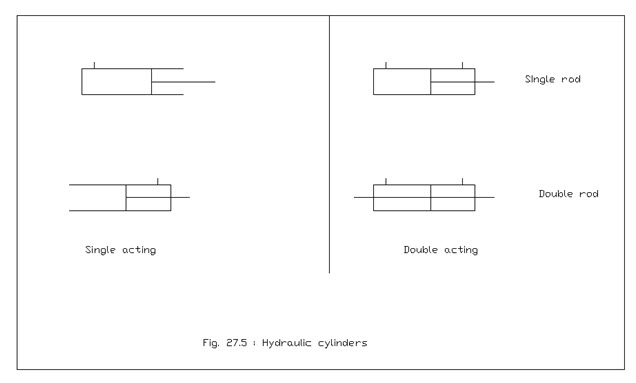
Cylinder
A simple rectangle is the symbol for cylinder but it is different for different types of cylinders and is as below-
Single acting cylinder
One of the cylinder is open in the cylinder symbol
Double acting cylinder
Both ends of the cylinder are closed in the cylinder symbol
Double end rod cylinder
A rod line extends from each end of the basic cylinder symbol.
Pressure-Control Valves
The pressure control valve is given the symbol as a square with external port connections. An arrow inside shows the direction of flow of fluid.
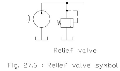
Relief Valve
The relief valve's symbol goes between the pressure line and the tank. The flow-direction arrow points away from the pressure-line port and toward the tank port. When pressure in the system overcomes the valve spring, flow is from the pressure port to the tank port
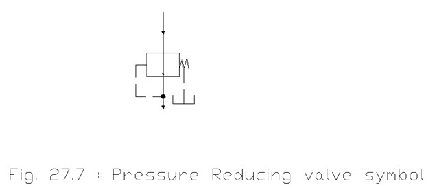
Pressure Reducing Valve
It is a unit which gives nearly constant output pressure provided that the inlet pressure remains higher than the required outlet pressure. The symbol indicates the outlet pressure opposite the spring
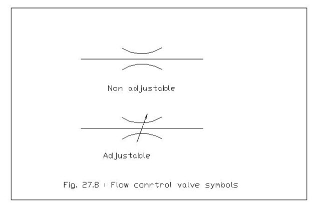
Flow Control Valve
This type of valve may be with fixed output in which variations in inlet pressure do not affect rate of flow will have the different symbols for the basic flow control valve, adjustable and nonadjustable valves.
Directional Control Valves
These are the valves which provide full or restricted flow by opening or closing of one or more paths .A directional control valve symbol uses a multiple envelope system. It has separate rectangle for each position. All the port connections are made to the envelope, which shows the neutral condition of the valve. It is also having the arrows in each envelope which indicates the flow paths when the valve is moved to that position.
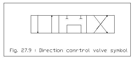
Direction control valve
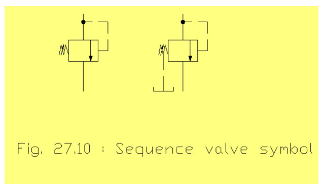
Sequence valve
In a sequence valve the inlet port is connected to a primary cylinder and the outlet port is connected to the secondary cylinder. This valve is drained externally and therefore drain connection is added to the symbol.
Last modified: Thursday, 27 March 2014, 5:38 AM