Site pages
Current course
Participants
General
Module 1. Dairy Development in India
Module 2. Engineering, thermal and chemical proper...
Module 3. Unit operation of various dairy and food...
Module 4. Working principles of equipment for rece...
Module 5. Dairy plant design and layout, compositi...
Module 6. Deterioration in products and their cont...
Module 7. Physical, chemical and biological method...
Module 8. Changes undergone by the food components...
Module 9. Plant utilities requirement.
References
Lesson 30. Compressed Air, Water And Steam
30.1 INTRODUCTION:
Dairy and Food plant have different requirements to run the plant. Different machineries need different engineering services for smooth running. We can classify utilities in major five parts, compressed air, Water, Steam, Refrigeration system and Electricity.
30.2 Compressed Air:
The dairy and Food industry has an extensive requirement for advanced instruments and equipment for automatic control, monitoring and regulation of the different production processes. Compressed air also has other applications such as powering the actuators on some machines, such as filling machines, emptying product from pipes, agitation in storage tanks and, operating compressed air tools in the workshops. Pneumatically controlled automatic systems have proved reliable in industry and are frequently used. The reliability requires compressed air free from impurities, which places demand on the design of the compressed air system.
30.2.1 Requirements of compressed air:
Compressed air, used for pneumatic tools, etc should be free from solid particles and as dry as possible. The supply pressure should be approximately 600 kPa.
Compressed air which does not come into contact with the product, used for the control of instruments and as source of power to active pneumatic components and valves etc. must be clean, dry, and preferably oil-free which supply at a pressure between 500 and 600 kPa (5 – 6 bar).
Compressed air which comes into direct contact with the product should be clean, oil-free, dry, odorless and practically sterile. Such quality of air is used in relatively small quantity. The supply pressure should be between 200 and 300 kPa (2-3 bar).
30.2.2 Compressed Air Production:
Air compressors are used to provide the compressed air. A compressor will usually consumes its purchase price in electricity consumption every year and therefore selecting and efficiently operating the correct type of compressor for the application can substantially reduce operating costs. Installing a control sequencing system on multiple compressors will help the system to respond more efficiently to varying loads. Variable-speed compressors can reduce power with reduced demand.
The Compressed air system consists of intake air filters, compressors, inter-state coolers, air dryers, moisture drain traps, receivers, regulators and piping network. Compressor is the main component of the compressed air system. The performance of the compressed air supply system depends on the type of the compressor, selection of components, and maintenance aspects of the system.
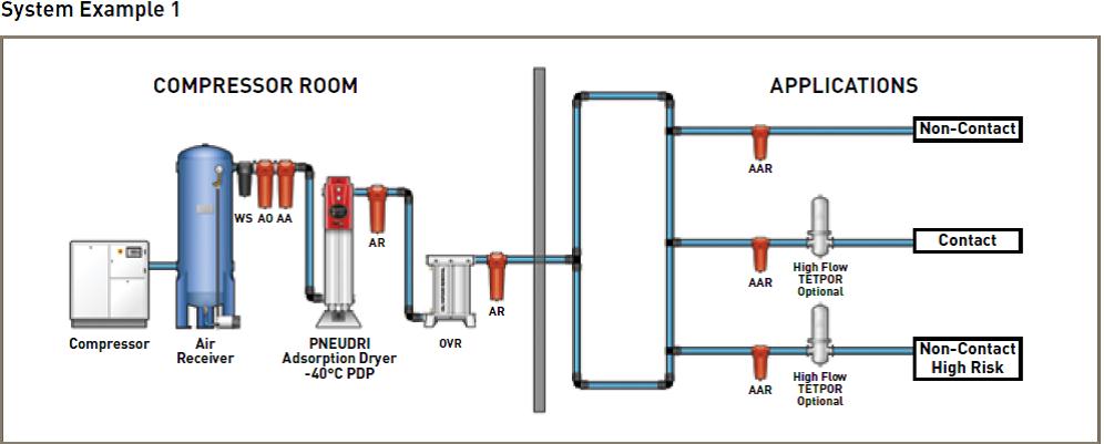
Figure 30.1: Schematic diagram of Compressed air producing unit
30.2.3 Compressor:
Reciprocating kind of compressors is widely used in compressed air generation. Depending upon the engineering aspects there are lubricating or non-lubricating, single or multiple cylinders, water cooled or air cooled. Single cylinder compressor is generally air cooled, while multiple cylinder compressors are water cooled. Water cooled compressors are more efficient than air cooled systems. Two stage compressors are used for high pressure and are characterized by lower discharge temperature. Multistage compressors may have lower specific power consumption compared to single stage compressor operating over the same total pressure difference. Among rotary compressor, screw compressors are widely used in dairy and food industry. Centrifugal compressors are better suited for application requiring very high capacities.
Compressor Performance:
Compressor efficiency can be evaluated as:
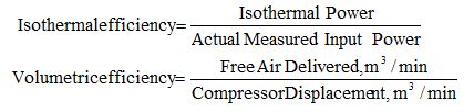
For practical purpose, the most efficient guide in comparing compressor efficiency is the specific power consumption (kW/Volume flow rate).
Capacity of compressor is the rated volume of flow of gas compressed and delivered. The compressor capacity can be evaluated by the following formula,
Considering isothermal compression,
30.2.4 Receiver:
The air receiver should be sized to give large cooling surface and even out the pulsation in air delivery. The minimum size of the receiver should be such that it can store the air equal to one minutes continuous output of the compressor. Another approximation can be to size the receiver volume to be 5% of the rated hourly free air output.
30.2.5 Air Dryer:
Air which has been compressed in a compressor will contain a great deal of water. It will also be hot (about 140 – 150 0 C) and must therefore be cooled. For this purpose, it passes through an after cooler, where most of the water is precipitated by means of cooling with water. The compressed air then continues to a cooler-drier, where further cooling takes place until a dew point of about of 2 0 C is reached.
30.2.6 Traps/ Moisture Separator:
The traps will be installed in air lines at all low points and dead ends to remove condensed moisture.
30.2.7 Piping System:
The piping system will be designed for a maximum allowable pressure drop of 5% from the compressor to the most distinct point of use. The piping system should be arranged in a closed loop to allow more uniform pressure distribution.
Sterile air is obtained by filtering the compressed air in sterile filters. The filter element of these filters consists of chemically pure cotton. Micro-organisms are killed as the air is heated in the compressor. Reinfection occurs in the pipes, and the sterile filters are therefore fitted immediately before the equipment where the air is used.
30.3 Water:
Water is one of the very essential services required for dairy and food plants. The water is necessary for cleaning of equipment and floor, washing operations like can washing, crate washing; preparation of hot water and chilled water as well as for preparation of soft water for boiler feed water. The ratio of water used to milk handled by dairy plants varies from 1 to 2 depending on the types of product manufactured by the plant. It is very important to reduce the water consumption in order to reduce the load on effluent treatment plant of the dairy. The source of water may be from open well, tube well or supply from any other agency. The microbial and chemical quality of water is more important for dairy plant. The hardness of water is concerned to dairy plant as it causes scale deposit in condenser and other heat exchanger. Therefore, it is necessary to treat the water in softening plant to reduce the hardness of water for the equipment requiring soft water. Water having hardness <35 ppm (35 mg/l) is considered as soft water though boiler feed water is treated to get hardness below 5 ppm.
30.3.1 Distribution of water:
The distribution of well water, chilled water and soft water in the food and dairy plants is requiring knowledge of hydraulics and need of such water at different points in the dairy and food plant. Water distribution net work is planned at the time of planning and erection work of the plant. The requirement of quantity of water, pressure, velocity etc. for different equipment is carefully estimated to design an appropriate water supply net work. This involves the estimation of pipe size and various fittings required for the supply of water. Water is distributed in GI pipelines. There are two basic methods for distribution of water.
Gravity water distribution
Hydro-flow water distribution system
30.3.1.1 Gravity water distribution:
The water from the tube well or open well is pumped to an over head tank constructed for storage and distribution of water. The capacity of the tank and the height varies depending on the requirement of the plant. The rate of discharge of water from any pipeline depends on the velocity of water and the diameter of the pipeline. The available head of water which is decided by the height of water tank as well as major and minor head losses decides the velocity of the water in the pipeline. The size of main pipeline is carefully calculated to supply water in all branches of the pipes.
30.3.1.2 Hydro-flow water distribution system:
The hydro-flow water distribution system consists of a hydro flow air tight tank, centrifugal pumps and underground water sump. The water from the tube well is stored in the big capacity underground sump. This water is pumped in the hydro flow tank which is equipped with a pressure switch to stop the centrifugal pump at some cut out pressure (say 6 bar). The air pressure above the surface of water in the tank gives required head for the supply of water. As the water quantity is reduced from the tank, the pressure of the tank falls (say 3 bar) which activates the pressure switch to start the water pump again to fill the tank. Thus, the pressure head in the hydro-flow tank is maintained between two pressure limits based on the setting of the pressure switch. This method of water distribution can be made complete automatic to start submersible pump based on the level sensors provided in the sump and operation of centrifugal pump to feed water in the hydro-flow tank. In addition to this, this system does not involve heavy construction cost which is required in gravity supply system. A schematic diagram of a hydro flow water supply system is shown in Fig. 30.1
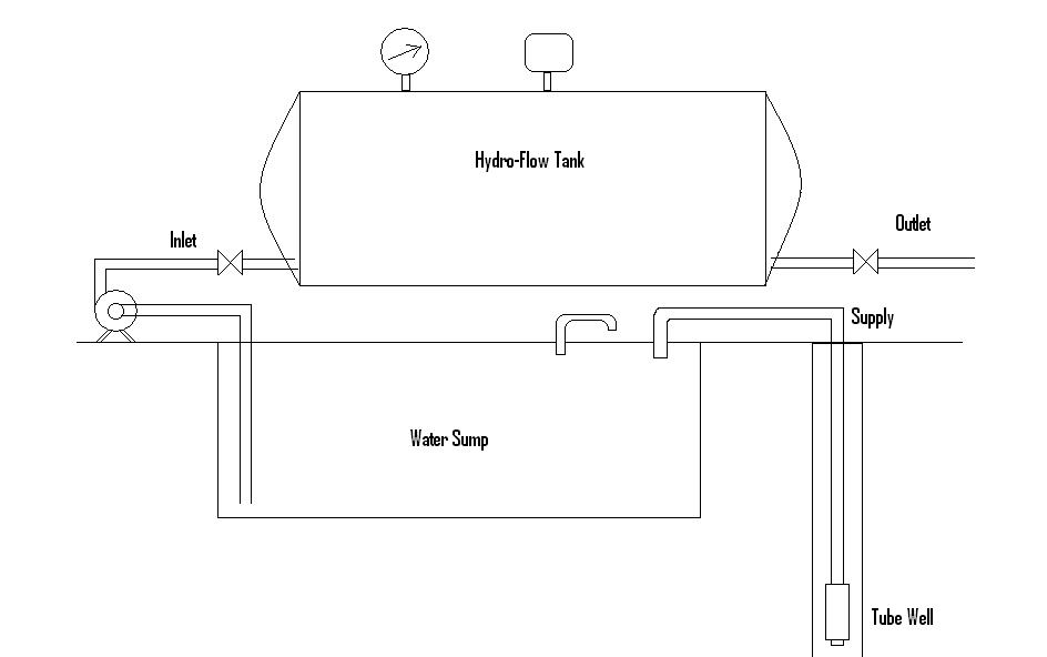 Fig. 30.2_ Hydro Flow Water Distribution System
30.3.2 Measuring water consumption
To understand how to manage water effectively it is essential to understand how much water enters and leaves the factory and where it is being used. There are a number of methods that can help to quantify water use and develop a water model:
Install flow meters in strategic areas to directly measure water use.
Use a bucket and stopwatch to estimate flow from pipes or hoses.
Use manufacturers’ data to estimate water use for some equipment and compare with actual water use.
Use known operational data to estimate water use (e.g. a 10 kL tank fills every wash cycle). When identifying areas of water use, manual operations as well as equipment should be monitored carefully (e.g. the volume of water used for washing down floors and equipment must be taken into account). It is also a good opportunity to observe staff behavior (e.g. taps left running or hoses left unattended).
30.4 Steam:
Steam is an excellent medium for conveying heat in dairy and food plants. It is the most economical and common source of heat energy, and has been adapted by all the milk processing plants It is used for processing, cleaning and sterilization of process equipments.
30.4.1 Steam Requirement in Dairy:
Considerable quantity of steam is required for processing, heating, cleaning, and sterilization in dairy. Low pressure steam (below 2 kg/cm2 abs) can be used where temperature up to 115°C is required. Low pressure steam is less expensive because of reduced labor charge, fuel cost and maintenance costs. Low pressure steam requires large pipe size.
30.4.2 Formation of Steam and Its Properties:
Steam is vaporized water, which is formed by adding sufficient heat or reducing pressure. When water is heated vaporization occurs because the vapour pressure of the liquid exceeds the vapour pressure of the surrounding atmosphere.
Consider 1 kg of water at 0 0C, contained in a closed vessel, is heated slowly. The volume of water will increase slightly with the increase in temperature. On further heating, temperature reaches boiling point, i.e., 100 0C. When the boiling point is reached, the temperature remains constant and the water evaporates. The vapour will have some particles of water in suspension, and it termed as wet steam. This process will continue till the whole water is converted into wet steam. On further heating, the water particles in suspension will be converted into steam, which is dry or saturated steam. If the dry steam is further heated, its temperature starts rising, and steam is such a state is termed superheated steam.
30.4.2.1 Wet steam: when the steam contains moisture or water particles are suspension, it is called wet steam.
30.4.2.2 Dry saturated steam: when the wet steam is further heated and all the suspended water has evaporated, it is known as dry saturated steam.
30.4.2.3 Superheated steam: when the dry steam is further heated at a constant pressure, thus raising its temperature, it is said to be superheated steam. Since the pressure is constant, the volume of superheated steam increases.
30.4.2.4 Sensible heat of water: It is the amount of heat absorbed by 1 kg water, when heated at constant pressure, from 0 0C to boiling point or saturation temperature (ts). the sensible heat is also known as liquid heat or total heat of water, usually denoted by h.
30.4.2.6 Latent heat of vaporization: It is the amount of heat absorbed to evaporate 1 kg of water at its boiling point, without change in temperature, usually denoted by L. Its value depends upon the pressure and is 539 kcal/kg at atmospheric pressure.
30.4.2.7 Total heat or enthalpy of steam: It is the amount of heat absorbed by water from its freezing point to saturation temperature plus the heat absorbed to evaporate water at its boiling point. The total heat or enthalpy of steam is sensible heat + latent heat, denoted by H.
30.4.2.8 Specific volume: It is the volume occupied by the steam per unit mass at a given temperature and pressure, and is expressed in m3/kg. The value of specific volume decreases with the increase in pressure.
30.4.3 Fuel:
The fuels may be classified as solid, liquid or gaseous fuels. Each of these may be further sub-divided as natural or prepared fuels. The natural solid fuels are wood, peat, lignite or brown coal, bituminous coal, and anthracite coal. The prepared solid fuels are wood charcoal, coke, Briquetted coal and pulverized coal. The liquid fuels are derived from natural petroleum or crude oil with the chief combustible ingredients being carbon and hydrogen. The natural gas consists of marsh gas, methane (CH4) together with small amount of other gases such as ethane, carbon dioxide, and carbon monoxide.
30.4.4 Steam Boilers:
A steam generator or boiler is a closed pressure vessel used to generate steam. Its function is to transfer the heat produced by combustion of fuel to water and ultimately to generate steam. It consists of the boiler shell, combustion chamber, grate, furnace, heating surface, mountings and accessories. A good steam boiler should produce maximum quantity of steam with the given fuel, economical to install, high efficiency, occupy small space, safe in working, capable of quick starting, meet the load fluctuations, light in weight, easily accessible for inspection and repair, proper arrangement of circulation of water and hot gases. Selection of type of boiler and size of a boiler depends upon the capacity, working pressure, availability of fuel and water, load factor and available space, initial cost, operating cost and maintenance cost.
30.4.4.1 Classification of Boilers
The boilers may be classified according to the Content in the tube: fire tube and water tube, Position of the furnace: internally fired and externally fired, Axis of the shell: vertical and horizontal, Number of tubes: single tube and multi tubular, Method of water and steam circulation: natural and forced circulation, Use: stationary and mobile, Type of fuel: solid, liquid or gaseous fuel.
30.4.4.2 Air Requirement
Adequate supply of oxygen is essential for complete combustion to obtain the maximum amount of heat from the fuel. One kg of carbon requires 8/3 kg oxygen; 1 kg of hydrogen requires 8 kg of oxygen, and 1kg sulfur requires 1 kg of oxygen for its complete combustion. The total oxygen requirement for complete combustion of 1 kg of fuels is {(8/3) C + H2 + S} kg.
30.4.4.3 Boiler Efficiency
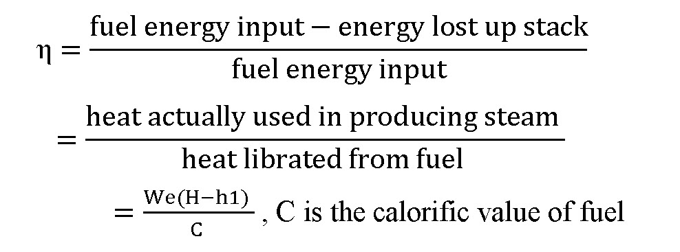
The boiler efficiency can be figured directly from the total fuel burned in a given period and the total water evaporated into steam in the same period. Another method is from data on heat lost up by the stack. It is the ratio of heat actually used in producing the steam to the heat liberated in the furnace. It is also known as the thermal efficiency of the boiler. Boiler efficiency or thermal efficiency is denoted by η.
Last modified: Thursday, 22 August 2013, 9:50 AM