Site pages
Current course
Participants
General
Module 1. Dairy Development in India
Module 2. Engineering, thermal and chemical proper...
Module 3. Unit operation of various dairy and food...
Module 4. Working principles of equipment for rece...
Module 5. Dairy plant design and layout, compositi...
Module 6. Deterioration in products and their cont...
Module 7. Physical, chemical and biological method...
Module 8. Changes undergone by the food components...
Module 9. Plant utilities requirement.
References
Lesson 32. Electrical Energy And Distribution System
32.1 Introduction
Electric power has become so common place in the dairy industry that modern plants could not operate without this power source. In fact, most plants of significant size have acquired “back-up” electrical power generators to use in case disruptions occur in the primary supply. The electric power represents the most versatile and flexible power source available. In addition, the cost of electric power is very attractive when compared with other sources.
32.2 Electrical Terms and Units
Electricity has its own set of terms and units. These terms and units are entirely different from most physical systems, and it requires careful analysis to relate the terms to applications. The following terms are essential to deal with electrical energy.
Electricity can be defined as the flow of electrons from atom to atom in an electrical conductor. Most materials can be considered conductors, but will vary in the ability to conduct electricity.
Ampere is the unit used to describe the magnitude of electrical current flowing in a conductor. By definition, 1 ampere (A) is 6.06 ×10¹⁸ electrons flowing past a given point per second.
Voltage is defined as the force causing current flow in an electrical circuit. The unit of voltage is the volt (V).
Resistance is the term used to describe the degree to which a conductor resists current flow. The ohm (Ω) is the unit of electrical resistance.
Direct current is the type of electrical current flow in a simple electrical circuit. By convention, current is considered to flow from a positive to a negative terminal of a voltage generator.
Alternating current describes the type of voltage generated by an AC (alternating current) generator. Measurement of the actual voltage generated would indicate that the magnitude varies with time and a uniform frequency. The voltage ranges from positive to negative values of equal magnitudes. Most electrical service in the India operates at 50 cycles per second (50 Hz).
Single-phase is the type of electrical current generated by a single set of windings in a generator designed to convert mechanical power to electrical voltage. The rotor in the generator is a magnet that produces magnetic lines as it rotates. These magnetic lines produce a voltage in the iron frame (stator) that holds the windings. The voltage produced becomes the source of alternating current.
Three-phase is the type of electrical current generated by a stator with three sets of windings. Since three AC voltages are generated simultaneously, the voltage can be relatively constant. This type of system has several advantages compared with single-phase electricity.
Watt is the unit used to express electrical power or the rate of work. In a direct current (DC) system, power is the product of voltage and current, whereas computation of power from an alternating current (AC) system requires use of a power factor.
Power factors are ratios of actual power to apparent power from an alternating current system. These factors should be as large as possible to ensure that excessive current is not carried through motors and conductors to achieve power ratings.
Conductors are materials used to transmit electrical energy from source to use. Ratings of conductors are on the basis of resistance to electrical flow.
32.3 Ohm’s Law
The most basic relationship in electrical power use is Ohm’s 1 law, expressed as
Ev = IRE , where the voltage Ev is equal to the product of current I and resistance RE.
As might be expected, this relationship illustrates that for a given voltage, the current flow in a system will be inversely proportional to the resistance in the conductor. As indicated earlier, the power generated is the product of voltage and current.
Power = EvI
Power = I2RE
Power = Ev2/RE
These relationships can be applied directly to direct current (DC) systems and to alternating current (AC) with slight modifications.
32.4 Electric Circuits
The manner in which conductors are used to connect the electric power source to the point of use is the electrical circuit. There are three basic types of circuits, with the series circuit being the simplest. As indicated by Figure 32.1, this type of circuit is recognized as having the resistances connected in series with the power source. In this type of situation, each resistance would probably represent the points at which the electrical power is used. Often, these points are referred to as electrical loads.
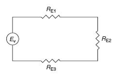
Figure 32.1: Electrical circuit with resistance in series.
Application of Ohm’s law to this situation leads to
Ev = I (RE1 + RE2 + RE3)
indicating that resistances in series are additive. In addition, the voltage is often expressed as the sum of the voltage drop across each resistance in the circuit.
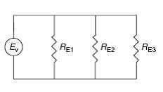
Figure 32.2: Electrical Circuit with resistance in parallel
A parallel electrical circuit has the resistance or loads connected in parallel with the power source, as illustrated in Figure 32.2. When Ohm’s law is applied to the parallel circuit, the following relationship applies:
Ev = I / [1/RE1 + 1/RE2 + 1/RE3]
With the inverse of each resistance being additive. The most complex basic electrical circuit has a combination of series and parallel resistances, as illustrated in Figure 32.3.
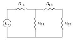 Figure 32.3: Electrical circuit with resistance in series and in parallel
To analyze relationships between voltage and resistances, the combination circuit must be treated in two parts. First, the three resistances (RE1, RE2, RE3) must be resolved as an equivalent Re.
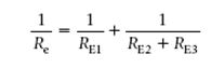
Then the circuit can be analyzed by applying Ohm’s law in the following manner:
Ev = I(RE4 +Re)
since in the modified circuit, the resistance RE4 and Re are in series.
32.5 Electric Motors
The basic component of an electric energy utilization system is the electric motor. This component converts electrical energy into mechanical energy to be used in operation of processing systems with moving parts.
The majority of the motors used in food processing operations operate with alternating current (AC), and their operation depends on three basic electrical principles. These principles include the electromagnet, formed by winding insulated wire around a soft iron core. Current flow through the wire produces a magnetic field in the iron core; orientation of the field is dependent on the direction of current flow.
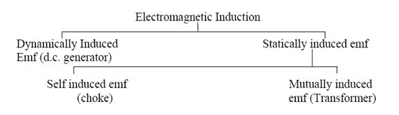
The second electrical principle involved in the operation of a motor is electromagnetic induction. This phenomenon occurs when an electric current is induced in a circuit as it moves through a magnetic force field. The induced electric current produces a voltage within the circuit, with magnitude that is a function of the strength of the magnetic field, the speed at which the current moves through the field, and the number of conductor circuits in the magnetic field.
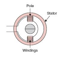
Figure 32.4: Schematic diagram of a stator
The third electrical principle is alternating current. This term refers to a current that changes direction of flow in a consistent manner. Normal electric service in the India is provided at 50 Hz, indicating that the change in current flow direction occurs 50 times per second. An electric motor contains a stator: a housing that has two iron cores wound with insulated copper wire. The two cores or windings are located opposite one another, as illustrated in Figure 32.4, and the leads from the windings are connected to a 50 Hz alternating current source. With this arrangement, the stator becomes an electromagnet with reversing polarity as the current alternates. Another component of an electric motor is the rotor: a rotating drum of iron with copper bars. The rotor is placed between the two poles or windings of the stator (Fig. 32.5). The current flow to the stator and the resulting electromagnetic field produces current flow within the copper bars of the rotor. The current flow within the rotor creates magnetic poles, which in turn react with the magnetic field of the stator to cause rotation of the rotor. Due to the 50 Hz alternating current to the stator, the rotation of the rotor should be 3600 revolutions per minute (rpm), but it typically operates at 3450 rpm. Although there are numerous types of electric motors, they operate on these same basic principles. The most popular motor in the food processing plant is the single-phase, alternating current motor. There are different types of single-phase motors; the differences are related primarily to the starting of the motor.
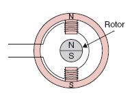
Figure 32.5_ Schematic diagram of stator with rotor
The selection of the proper motor for a given application is of importance when ensuring that efficient conversion of electrical to mechanical energy occurs. The selection process takes into account the type of power supply available, as well as the use of the motor. The type and size of load must be considered, along with the environmental conditions of operation and the available space.
32.6 Electrical Controls
The efficient use of electrical energy and the equipment that is operated by this energy source is related to the opportunity for automatic control. Since the operation of processes and equipment in a food processing plant depends on responses to physical parameters, automatic control involves conversion of the physical parameter into an electrical response or signal. Fortunately, these conversions can be achieved rather easily using a variety of electrical transducers.
32.7 Electric Lighting: Another primary use of electric power in dairy processing plants is to provide illumination of work spaces.
32.8 Process Controls in Food Processing
A typical food processing factory involves a number of unit operations that are carried out with different processing equipment: pumping, mixing, heating, cooling, freezing, drying, and packaging. Often the processing equipment operates in a continuous mode, which results in higher processing efficiencies than the batch mode. In designing a food processing plant, the processing equipment is arranged in a logical manner so that as raw food enters the plant, it is conveyed from one piece of equipment to the next while undergoing the desired processing.
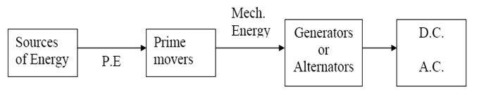
32.9 Power Generation and Distribution
32.9.1 Generation of electrical Energy
32.9.2 Sub-station
The electrical energy is generated in different types of generating stations located at distant places from the consumer’s premises. For example, Some nuclear and coal fired based thermal power generating stations are commissioned far away from the populated area from safety point of view. So, to transfer such a huge quantum of electrical energy from generating stations to the ultimate consumer, number of transformers and other switching equipments are required to step up or step down the voltage. Any station comprising of transformers and switching equipment is known as sub-station. In general the sub-station is of following three types:
- Pole Mounted Type Sub-station
- Outdoor Type Sub-station
- Indoor Type Sub-station
Transmission and Distribution:
High voltage transmission lines are economical which decreases line losses, save copper and increases Efficiency of transmission. Practical working voltage has limit due to increase in cost of switch gear, transformer etc.
32.9.3 Transformer
A transformer is a static electrical device used to transfer electrical power from one circuit to another keeping the supply frequency constant. We can increase or decrease the voltage in the secondary of the transformer with the corresponding changes in current and hence the power transfer will be almost constant if we neglect the losses. This transfer of power and change in secondary voltage will take place due to linkage of common magnetic flux and mutual induction between the two coils as explained below in working principle of transformer.
Working Principle: A transformer works on the principle of Faraday’s laws of electro magnetic induction, which states that “whenever a closed circuit coil is placed in an alternating magnetic field, an electro motive force (e.m.f.) will be induced in that coil and magnitude of this induced e.m.f. will depends upon the number of turns in the coil.”
When the primary winding of the transformer is connected to A.C. supply, the magnetic flux (F) will be set up and circulate in the laminated magnetic core. This magnetic flux will be alternating in nature as the supply frequency and links with both the windings (Primary and secondary) of the transformer. Now according to faraday’s laws of electromagnetic induction an e.m.f. will be induced in the secondary winding due to mutual induction. This induced e=ndF/dt in the secondary winding will depend upon the rate of change of flux and number of turns. If the number of turns in the secondary winding is greater than primary, the transformer will act as step up transformer and vice-versa. Whether a transformer is step up or step down depends upon the transformation ratio (K).
32.10 Distribution Transformer
A distribution transformer is used to step down the 11 kv A.C. supply to 230/440 volts A.C. and are available in different KVA rating depending upon the requirement of the consumers. The main parts of a distribution transformer are, Primary Winding, Secondary Winding, Transformer Oil, Conservator, Breather, Oil Drain Point, Cooling Tubes, Oil Level Indicator, Earth point, Explosion Vent, Tap Changer, etc.
32.11 Distribution System
The system used to distribute the electrical energy to various consumers safely is known as distribution system. Generally 3-phase 4-wire A.C. system is adopted for distribution of electrical energy in industries where as single-phase two-wire system is used in home, offices and commercial purpose. There are three different systems of power distribution system: Single Phase Two wire System, Three Phase Three wire System and Three Phase Four wire System.
32.12 Power Factor
“Cosine of the angle between applied voltage and current drawn in any electrical circuit is known as power factor” and it is denoted by “Cos Φ”. When a purely resistive circuit is connected across the A.C. supply, the current drawn from the main supply will be in phase with applied voltage and hence the power factor will be unity. But in case of purely inductive and capacitive circuit, the current drawn will lag behind and lead the applied voltage, by an angle of 900 respectively.
32.13 Work, power and energy:
Joule’s Law of Electric Heating: The amount of work required to maintain a current of I A through a resistance of R ohm for t second is
Work done = I2Rt joules = VIt joules (because R=V/I)
= Wt joules (because Watt = VI)
= V2t /R joules (because I = V/R)
This work is converted into heat
The amount of heat produced = H = Work done /Mechanical equilibrium of heat = W.D./J
Where, J = 4186 joules/kcal = 4200 joules/ kcal
So, H = I2Rt/4200 kcal = V2t/4200 R kcal.
In other world: The heat energy evolved in t second is directly proportional to the magnitude of the resistance(R) and square of the current (I)
H ∞ I2Rt so, H = I2Rt / J, J = Joule’s constant
Thermal Efficiency:
η = Useful heat / Total heat
= [m s ( θ2 – θ1) / (VIt / J)]
Work: Work is said to be done by a force when it moves the body through a certain distance.
:. W = F x d Nm or jaule
Power: Power is rate of doing work
:. Power= Work/time J/S = Watt
Horse Power (metric): Rate of doing work of 75 kg f m/s
:. 1 hp (metric) = 735.5 J/S (W) & 1 hp (British) = 746 J/S (W)
Energy: It is the capacity to do work. Same unit as work i.e. joule, 1 kwh = 36x10 5J = 860 kcal
Last modified: Saturday, 5 October 2013, 10:41 AM