Site pages
Current course
Participants
General
Module 1_Fundamentals of GW
Module 2_Well Hydraulics
Module 3_Design, Installation and Maintenance of W...
Module 4_Groundwater Assessment and Management
Module 5_Principle, Design and Operation of Pumps
Module 6_Performance Characteristics, Selection an...
Keywords
Lesson 16 Design of Tubewells and Gravel Pack
16.1 Introduction
Proper design of water wells (tubewells and open wells) is essential in order to obtain optimum quantity of groundwater economically from a given aquifer system. The choice of open wells or borewells (tubewells) mainly depends on the economic condition of users, depth to groundwater availability and the quantity of water required. However, the availability of groundwater in a region depends on several factors such as geologic setting, geomorphology, rainfall, climate, topography, soil, drainage density, land use/land cover and vadose zone condition. Therefore, proper groundwater exploration and hydrogeologic investigation are pre-requisite to the design of water wells.
Major steps involved in the design of tubewells are: (i) selection of suitable size of the well and casing; (ii) length and location of the screen, including slot size and shape, and percentage of opening; (iii) selection of casing and screen material, and (iv) design of gravel pack (if gravel pack is necessary). These design steps are discussed in subsequent sections. Generally, the design of tubewells requires more design details than that of open wells. Also, tubewells in unconsolidated geologic formations involve consideration of more design details as compared to the wells in consolidated geologic formations (i.e., fractured/fissured rocks). Well designed water wells (tubewells or open wells) intend to ensure proper performance of the wells, reduced pumping and maintenance costs, and long service life of the well. This lesson focuses on the design of tubewells and gravel pack only. For the design of open wells in unconsolidated and hard rock formations, interested readers are referred to Michael et al. (2008).
16.2 Well Diameter
The size of a well needs to be carefully selected because it considerably affects the cost of well construction. It should be large enough to accommodate the pump used for groundwater withdrawal with a proper clearance (at least 5 cm) for installation and efficient operation. In deep wells which have both large static and pumping water levels, the well diameter can be reduced below the level of the lowest pump setting during dry periods, especially in the confined aquifers having relatively high piezometric level.
From the Thiem equation, it is apparent that for the same drawdown in the pumping well, the well yield is inversely proportional to, where R0 is the radius of influence and rw is the radius of the pumping well. Considering R0 = 300 m, a pumping well of 60 cm diameter will yield 12% more than the well of 30 cm diameter. This demonstrates that drilling a large diameter well will not necessarily mean proportionately large yields. Table 16.1 summarizes the recommended diameters of pumping wells for various expected well yields.
Table 16.1. Recommended well diameters (Source: Raghunath, 2007)
|
Sl. No. |
Expected Well Yield (L/min) |
Internal Diameter of Well Casing (cm) |
Nominal Size of Pump Bowl (cm) |
|
|
Minimum |
Optimum |
|||
|
1 |
400 |
12.5 |
15 |
10 |
|
2 |
400 - 600 |
15 |
20 |
12.5 |
|
3 |
600 - 1400 |
20 |
25 |
15 |
|
4 |
1400 - 2200 |
25 |
30 |
20 |
|
5 |
2200 - 3000 |
30 |
35 |
25 |
|
6 |
3000 - 4500 |
35 |
40 |
30 |
|
7 |
4500 - 6000 |
40 |
50 |
35 |
|
8 |
6000 - 10000 |
50 |
60 |
40 |
16.3 Well Depth
The depth of a pumping well depends on the depth at which aquifer layers exist and the number of aquifers to be tapped; this information could be obtained from the well logs (also called ‘lithological logs’) of an area. Usually, a pumping well is drilled up to the bottom of the aquifer so as to obtain greater well yield. If multiple aquifer layers exist in an area and money is not a constraint, pumping wells are drilled to penetrate two or more aquifer layers so that large well yield can be obtained for a longer time period. The poor-quality aquifer, if available, is backfilled or sealed in order to avoid the upward migration of the poor-quality groundwater when the well is pumped.
16.4 Design of Well Screen
The design of a well screen (also known as ‘strainer’) involves the determination of screen length, location of the screen, percentage open area, size and shape of openings (slots), screen diameter, and the selection of screen material. These design points are discussed in subsequent sub-sections.
16.4.1 Location and Length of the Screen
The length of a well screen is selected in relation to the aquifer thickness, available drawdown and stratification of the aquifer. In homogeneous confined aquifers, about 70 to 80% of the aquifer thickness is screened (Raghunath, 2007). The screen should best be positioned centrally at an equal distance between the top and bottom of the aquifer. In the case of heterogeneous confined and unconfined aquifers, it is better to screen the most permeable strata. On the other hand, in the case of homogeneous unconfined aquifers, the well screen is best positioned in the bottom portion of the aquifer. Selection of screen length is actually a compromise between two factors viz., specific capacity of the well and drawdown in the well. A higher specific capacity can be obtained by using as long a screen as possible, while more drawdown results by using short screens. The theory and experience have shown that screening the bottom one third of the aquifer provides the optimum design of a screen.
16.4.2 Size and Shape of Slots
The size and shape of the openings (slots) in the screen depend on the gradation, and the size and shape of the aquifer material so as to avoid entering of fine particles into the screen openings and to ensure that all the fine particles around the screen are washed out to improve the permeability of the aquifer material. For naturally developed wells, the size of the opening is selected as 40 to 70% of the size of the aquifer material (Raghunath, 2007). If the opening size selected on this criterion is smaller than 0.75 mm, then the use of an artificial gravel pack becomes essential.
16.4.3 Screen Diameter
After the length of the screen and the slot size has been selected, the screen diameter should be selected. Well screens (strainers) are available in a range of diameters. Suitable screen diameter is selected based on the desired yield of the well and the thickness of the aquifer. Recommended minimum diameters for well screens and casings are summarized in Table 16.2. Also, the entrance velocity near the well screen should not exceed 3 to 6 cm/s in order to avoid incrustation and corrosion and minimize friction losses (Raghunath, 2007). The entrance velocity is calculated by dividing the expected well yield with the total area of openings in the screen length.
Since the aquifers consisting of fine-grained materials tend to clog more easily than the aquifers consisting of coarser materials, it has been found that there exists a relationship between aquifer hydraulic conductivity and screen entrance velocity as shown in Table 16.3. To express the screen entrance velocities given in Table 16.3 in terms of screen size, the following equation can be used (Todd, 1980):
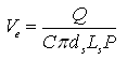 (16.1)
Where, Ve = optimum screen entrance velocity, Q = discharge of the pumping well, C = clogging coefficient (usually estimated at 0.5 on the basis that approximately 50% of the open area of a screen will be clogged by the aquifer material), ds = diameter of the screen, Ls = length of the screen, and P = percentage of open area in the screen (available from the manufacturer’s specifications).
Thus, for a given aquifer material, aquifer thickness, well yield and type of well screen, an appropriate diameter and length of well screen could be selected.
Table 16.2. Recommended minimum diameters for well casings and screens (Source: U.S. Bureau of Reclamation, 1977)
|
Sl. No. |
Well Yield (m3/day) |
Nominal Pump Chamber Casing Diameter (cm) |
Surface Casing Diameter (cm) |
Nominal Screen Diameter (cm) |
|
|
Naturally Developed Wells |
Gravel-Packed Wells |
||||
|
1 |
<270 |
15 |
25 |
45 |
5 |
|
2 |
270 - 680 |
20 |
30 |
50 |
10 |
|
3 |
680 - 1900 |
25 |
35 |
55 |
15 |
|
4 |
1900 - 4400 |
30 |
40 |
60 |
20 |
|
5 |
4400 - 7600 |
95 |
45 |
65 |
25 |
|
6 |
7600 - 14000 |
40 |
50 |
70 |
30 |
|
7 |
14000 - 19000 |
50 |
60 |
80 |
35 |
|
8 |
19000 - 27000 |
60 |
70 |
90 |
40 |
Table 16.3. Optimum entrance velocity of water through well screens (Source: Walton, 1962)
|
Sl. No. |
Aquifer Hydraulic Conductivity (m/day) |
Optimum Screen Entrance Velocity (m/min) |
|
1 |
>250 |
3.7 |
|
2 |
250 |
3.4 |
|
3 |
200 |
3.0 |
|
4 |
160 |
2.7 |
|
5 |
120 |
2.4 |
|
6 |
100 |
2.1 |
|
7 |
80 |
1.8 |
|
8 |
60 |
1.5 |
|
9 |
40 |
1.2 |
|
10 |
20 |
0.9 |
|
11 |
<20 |
0.6 |
16.4.4 Screen Material
The selection of screen material depends on the diameter and depth of the well, the type of aquifer layer, and the chemical composition of aquifer materials which dictates the quality of groundwater. The mineral content of the water, presence of bacterial slimes and strength requirements are important factors, which influence the selection of screen material. The screen material should be resistant to incrustation and corrosion, and should have enough strength to withstand the column load and collapse pressure. The principal indicators of corrosive groundwater are: low pH, presence of dissolved oxygen, CO2 > 50 ppm, and Cl > 500 ppm (Raghunath, 2007). The principal indicators of incrusting groundwater are: total hardness > 330 ppm, total alkalinity > 300 ppm, iron content > 2 ppm, and pH > 8. Slime producing bacteria are often removed by chlorine treatment. This is followed by acid treatment to redissolve the precipitated iron and manganese.
As far as the choice of the screen material is concerned, steel has good strength, but it is not corrosion resistant. In contrast, brass has fair to good resistance to corrosion, but it has less strength than the steel. However, the strength of a well-made brass screen is adequate in most situations. Stainless steel has excellent strength and is highly resistant to most corrosive conditions. Well screens of corrosion resistant alloys such as Everdur metal, type 304 stainless steel and silicon red brass could be used for permanent installations (Raghunath, 2007). Different metals used for fabricating screens and their suitability in terms of resistance to corrosion are presented in Table 16.4.
Table 16.4. Corrosion resisting metals (Source: Raghunath, 2007)
|
Sl. No. |
Name of Metal |
Composition |
Cost Factor |
Colour of Finish |
Suitability |
|
1 |
Monel Metal |
70% nickel and 30% copper |
1.5 |
Bluish Silver |
High NaCl and DO as in seawater, normally not used for drinking water. |
|
2 |
Super Nickel |
70% copper and 30% nickel |
1.2 |
Bright nickel |
High NaCl and DO as in seawater, normally not used for drinking water. |
|
3 |
Everdur Metal (Silicon-bronze) |
96% copper, 3% silicon and 1% manganese |
1.0 |
Rich copper red |
High TH, NaCl (without DO), and Fe. Usually used for municipal and industrial production wells. Highly resistant to acid treatment. |
|
4 |
Stainless Steel |
74% l.c. steel, 18% chromium and 8% nickel |
1.0 |
Dark silvery steel |
Water containing H2S, DO, CO2, Fe and bacteria. Usually used in municipal and industrial production wells. |
|
5 |
Cupro Nickel |
70% copper, 29% nickel and 1% arsenic |
- |
Bright nickel |
- |
|
6 |
Silicon Red Brass |
83% copper, 16% zinc and 1% silicon |
- |
- |
Resistant to acid and corrosion. |
16.4.5 Type of Screens
The types of well screens are mainly decided based on the shape of screen openings (slots). Some of the commonly used screen types are shown in Figs. 16.1(a, b, c, d). The V-shape continuous-slot type of well screen is fabricated by winding cold-drawn wire, approximately triangular in cross-section, spirally around a circular array of longitudinal rods [Fig. 16.1(a)]. The V-shaped openings facilitate the fine particles to move into the well during development without clogging them. This type has the maximum percentage of open area per unit length of the screen, and the area of openings can be varied by adjusting the spacing of the wires wrapped (Raghunath, 2007). These screens are usually made of galvanished iron (GI), steel, stainless steel and various types of brass.
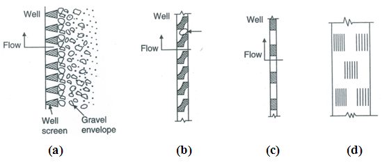
Fig. 16.1. Types of commonly used well screens: (a) V-shape continuous slot screen, (b) Louver-type screen, (c) Rectangular slot screen, and (d) Pipe-base well screen or Metallic filter point. (Source: Raghunath, 2007)
The Louver-type of screen has openings in the form of shutters [Fig. 16.1(b)], which are susceptible to be blocked by the fine particles during well development. Hence, this type of screen is most suitable for gravel-packed wells. The rectangular slot screen or the slotted pipe screen [Fig. 16.1(c)] is fabricated by cutting slots, vertical or horizontal, with a sharp saw, oxyacetylene torch, or by punching with a chisel and die or casing perforator. Some of the limitations of the slotted type well screens are wide spacing from the strength viewpoint, resulting in a low percentage of open area, lack of continuity and uniform size of the openings; the perforations made in the steel pipe may be more readily subject to corrosion at the jagged edges and surfaces, and the chance of blockage of such openings is high. This type of screen is least expensive. These days, slotted PVC pipes are widely used as screens, because especially in developing nations because they are light, cost effective, easy to handle, and free from corrosion. The use of slotted PVC pipes is generally limited to small diameter wells because of their relatively low strength and difficulty in providing proper fittings.
Furthermore, the pipe-base well screen or metallic filter point is made by using a perforated steel pipe [Fig. 16.1(d)]. A wire mesh is wrapped around the perforated pipe and is in turn is covered by a brass perforated steel. The percentage of open area in this type is normally low and the perforations are blocked by incrustation. This type of screen is relatively inefficient. In developing countries (including India), the coir-rope screen is sometimes used as an economical substitute for other types of screens. Coir rope is wrapped tightly around a circular array of steel flat, rods or bamboo strips. The life of the coir ranges from 7 to 8 years and can be increased by treating the coir with cashew shell oil (Raghunath, 2007). Hand boring sets are generally used for constructing the wells to be fitted with a coir-rope screen. The coir-rope screen does not require gravel packing and development, but still it gives very good water supply. This type of screen is most suitable for shallow wells (depth not exceeding 12 to 15 m) in deltaic regions.
The best type of screen opening is the V-shaped slot that widens towards the inside of the screen, i.e., openings are bevelled inside. A major factor in controlling head loss through a perforated well section is the percentage of open area. For practical purposes, a minimum open area of 15% is desirable, which is easily obtained with many commercial (manufactured) screens but not with pre-perforated casings (Todd, 1980). Therefore, manufactured screens are preferred to pre-perforated casings because of larger open area and the ability to tailor opening sizes to aquifer conditions.
16.5 Design of Gravel Pack
16.5.1 Natural Gravel Pack
In many situations, the grain-size distribution of aquifer material is such that a properly selected well screen allows finer particles to enter the well, and to be removed during well development. Thus, after the development of the well, coarser particles are retained outside the well screen and form a permeable envelope around the well screen which is known as a ‘natural gravel pack’ and the well is called a naturally developed well. If the uniformity coefficient  of an aquifer material for a naturally developed well (without an artificial gravel pack) is £5, the selected slot size should retain 40 to 50% of the aquifer material. However, if the uniformity coefficient (Cu) is greater than 5, the slot size should be selected such that it should retain 30 to 50% of the aquifer material (Todd, 1980).
16.5.2 Artificial Gravel Pack
A gravel-packed well is the well having an artificially placed gravel envelope around the well screen (Fig. 16.2). Salient advantages of the artificial gravel pack are (Todd 1980): (i) it stabilizes the aquifer tapped by the well, (ii) it avoids/minimizes sand pumping, (iii) it allows to use a large screen slot with a maximum open area, and (iv) it provides a zone of high permeability surrounding the well screen, which increases the well radius (known as ‘effective radius’ of the well) and well yield. When a well screen of a pumping well is to be surrounded by an artificial gravel pack, the size of the screen openings is decided based on the size of the gravel used for gravel packing.
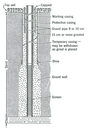
Fig. 16.2. Vertical cross-section of a gravel-packed well.
(Source: Todd, 1980)
Artificial gravel pack is required when the aquifer material is homogeneous with a uniformity coefficient (Cu) of less than 3 and an effective grain size (D10) of less than 0.25 mm (Raghunath, 2007). The pack-aquifer ratio (ratio of the 30 or 50% size of the gravel-pack material to 30 or 50% size of the aquifer material) should be 4:1 if the aquifer material is fine and uniform. However, if aquifer material is coarse and non-uniform, the pack-aquifer ratio should be 6:1. The gravel-pack material should have a uniformity coefficient (Cu) of less than 2.5. The design procedure for selecting the gravel material is to determine the point D30 of the gravel pack which is equal to 4 to 6 times the D30 of the aquifer material obtained from the sieve analysis of the aquifer material samples and then drawing a smooth curve through this point (corresponding to D30 of the gravel pack) representing a material with a uniformity coefficient of 2.5 or less. This is the gradation of the gravel pack to be used (Raghunath, 2007). The slot size of the well screen is selected as D10 of the gravel-pack material to avoid segregation of fine particles near the screen openings. The width of screen slots ranges from 1.5 to 4 mm and the length ranges from 5 to 12.5 cm. A pack-aquifer ratio of 5 (i.e., ratio of 50% size of the gravel-pack material and 50% size of the aquifer material) has been successfully used in water wells (Raghunath, 2007).
The maximum grain size of a gravel pack should be less than 1 cm and the thickness of the gravel pack should be between 10 and 20 cm (Raghunath, 2007). Generally, the size of the pea gravel varies from 4 to 8 mm. Although a variety of formulas have been developed, which relate gravel-pack grain-size gradations to aquifer grain-size gradations, the criteria for selecting gravel-pack material developed by the U.S. Bureau of Reclamation are shown in Table 16.5.
Table 16.5. Criteria for the selection of gravel pack material
(Source: U.S. Bureau of Reclamation, 1977)
|
Sl. No. |
Uniformity Coefficient of Aquifer (Cu) |
Gravel Pack Criteria |
Screen Slot Size |
|
1 |
<2.5 |
(a) Cu between 1 and 2.5 with the 50% size not greater than 6 times the 50% size of the aquifer.
(b) If (a) is not available, Cu between 2.5 and 5 with 50% size not greater than 9 times the 50% size of the aquifer. |
£ 10% passing size of the gravel pack |
|
2 |
2.5-5 |
(a) Cu between 1 and 2.5 with the 50% size not greater than 9 times the 50% size of the formation.
(b) If (a) is not available, Cu between 2.5 and 5 with 50% size not greater than 12 times the 50% size of the aquifer. |
£ 10% passing size of the gravel pack |
|
3 |
>5 |
(a) Multiply the 30% passing size of the aquifer by 6 and 9 and locate the points on the grain-size distribution graph on the same horizontal line.
(b) Through these points draw two parallel lines representing materials with Cu £ 2.5.
(c) Select gravel pack material that falls between the two lines. |
£ 10% passing size of the gravel pack |
The gravel selected for a gravel pack should be clean, dense, rounded, smooth and uniform, and should mainly consist of siliceous material (the allowable limit for calcareous material is up to 5%). Particles of shale, anhydrite and gypsum are also undesirable in the gravel-pack material. The detailed procedure for creating an artificial gravel pack is given in Todd (1980).
16.6 Design of Tubewells: An Example
Problem (Raghunath, 2007): A well log indicates that a clay layer of thickness 0-30 m from the ground surface is underlain by a layer of fine sand from 30 to 36 m and a layer of coarse sand from 36 to 45 m followed by a silt layer at the bottom. If the expected well yield is 900 L/min, design all the components of tubewells for both naturally developed and artificially gravel packed cases, assuming that: (a) groundwater occurs under confined conditions with a piezometric level of 6 m below the ground surface, and (b) groundwater occurs under unconfined (water table) conditions with a water table level of 30.6 m below the ground surface. The results of the sieve analysis of the geologic sample obtained from depths 36 to 45 m are summarized in Table 16.6 below.
Table 16.6. Results of the sieve analysis
|
IS Sieve Size |
Weight Retained on the Sieve (gm) |
Cumulative Weight Retained (gm) |
Cumulative Percentage Retained |
Cumulative Percentage Passing |
|
2.80 mm 2.00 mm 1.40 mm 1.00 mm 0.710 mm Bottom Pan |
57.4 112.2 84.8 59.6 43.2 41.3 |
57.4 169.6 254.4 314.0 357.2 398.5 |
14.4 42.4 63.6 78.5 89.3 100.0 |
85.6 57.6 36.4 21.5 10.7 0 |
|
Total |
398.5 |
- |
- |
- |
Solution:
Case 1: Tubewell in the Confined Aquifer
From Table 16.1, for an anticipated well yield (Q) of 900 L/min, a well casing diameter of 20 cm is recommended. The well screen should be located in the aquifer layer which lies between 36-45 m depths. The thickness of this aquifer is 9 m and it has a grain size mostly in the range of 0.6-2 mm and is classified as coarse sand according to the IS scale.
Length of the well screen, ![]() (considering the position of the screen at the three-fourth of the aquifer thickness).
(considering the position of the screen at the three-fourth of the aquifer thickness).
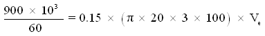
Considering 15% open area in the screen, the entrance velocity (Ve) for the well yield of 900 L/min can be calculated as:
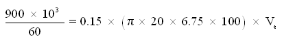
Ve = 2.358 cm/s, which is permissible.
Hence, a screen of 6.75 m length can be centrally located in the coarse sand aquifer. From the sieve analysis data of the aquifer sample, a grain-size distribution curve (or ‘grading curve’) is plotted on a semi-log paper (Fig. 16.3). From the grading curve, the effective size D10 = 0.69 mm and the uniformity coefficient Uc = 2.94. In this case, artificial gravel pack is not required since d10 > 0.25 mm and Uc > 2.5, and hence the well may be naturally developed when the screen slot size would be kept at D50 (i.e., 1.75 mm) to D60 (i.e., 2.03 mm), say 2 mm.
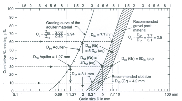
Fig. 16.3. Grain-size distribution curve illustrating the design of gravel pack. (Source: Raghunath, 2007)
Case 2: Tubewell in the Unconfined Aquifer
In this case also, the recommended well casing diameter will be 20 cm. Length of the well screen,![]() located at the bottom one-third of the coarse sand aquifer. Considering 15% open area in the screen, the entrance velocity (Ve) for the well yield of 900 L/min is calculated as:
located at the bottom one-third of the coarse sand aquifer. Considering 15% open area in the screen, the entrance velocity (Ve) for the well yield of 900 L/min is calculated as:
Ve = 5.305 cm/s, which is on the higher side.
Therefore, for a safer side, we should keep Ve within 3 cm/s. In order to bring the value of Ve below 3 cm/s, we can adopt a screen length of 4.5 m (i.e., half of the aquifer thickness) with a maximum open area of 18%. In this case, Ve is given as:
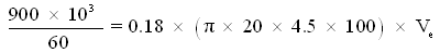
Ve = 2.947 cm/s, which is permissible.
Artificial gravel pack is not required and the slot size may be taken as 2 mm as in the case of confined aquifer (Case 1).
Design of Artificial Gravel Pack: If an artificial gravel pack is desired, as Cu for the coarse sand aquifer is < 3.0, D30 of gravel-pack material = 4 to 6 times D30 of the aquifer material which is 4 to 6 times 1.27 mm from the grain-size distribution curve (Fig. 16.3), i.e., 5.08 mm to 7.62 mm. With these points for D30 for the gravel-pack material, smooth curves are drawn such that Uc for the gravel-pack material is 2.5. The hatched area in Fig. 16.3 shows the recommended gravel-pack material; clean pea gravel of size 10 mm can be used. The slot size should be kept at D10 of the gravel-pack material, which is 4.2 mm. The thickness of the artificial gravel pack could be 15-20 cm.
Check for Drawdown: In the absence of field or laboratory value of aquifer hydraulic conductivity (K), it can be estimated by the Hazen’s formula as:
![]() cm/s.
cm/s.
Since the Hazen’s formula overestimates the value of K, let’s take two third of the above K value, i.e.,![]() cm/s.
cm/s.
Therefore, ![]() cm2/s.
cm2/s.
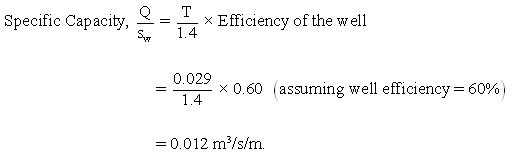
Note that the equations used for computing specific capacity of the well and aquifer hydraulic conductivity are approximate only; these estimates could be improved if more and better field data are available at the time of well design. Thus, we can estimate only probable drawdown in the well as follows:
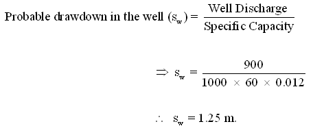
Thus, the probable drawdown in the well (sw) is reasonably low, and hence it is permissible.
References
-
Michael, A.M., Khepar, S.D. and Sondhi, S.K. (2008). Water Well and Pump Engineering. Second Edition, Tata McGraw Hill Education Pvt. Ltd., New Delhi.
-
Raghunath, H.M. (2007). Ground Water. Third Edition, New Age International Publishers, New Delhi.
-
Todd, D.K. (1980). Groundwater Hydrology. John Wiley & Sons, New York.
-
U.S. Bureau of Reclamation (1977). Groundwater Manual. U.S. Department of the Interior.
-
Walton, W.C. (1962). Selected Analytical Methods for Well and Aquifer Evaluation. Bulletin 49, Illinois State Water Survey, Urbana.
Suggested Readings
-
Todd, D.K. (1980). Groundwater Hydrology. John Wiley & Sons, New York.
-
Raghunath, H.M. (2007). Ground Water. Third Edition, New Age International Publishers, New Delhi.
-
Michael, A.M., Khepar, S.D. and Sondhi, S.K. (2008). Water Well and Pump Engineering. Second Edition, Tata McGraw Hill Education Pvt. Ltd., New Delhi.
-
Sarma, P.B.S. (2009). Groundwater Development and Management. Allied Publishers Pvt. Ltd., New Delhi.
Last modified: Friday, 14 March 2014, 11:21 AM