Site pages
Current course
Participants
General
Module 1_Fundamentals of GW
Module 2_Well Hydraulics
Module 3_Design, Installation and Maintenance of W...
Module 4_Groundwater Assessment and Management
Module 5_Principle, Design and Operation of Pumps
Module 6_Performance Characteristics, Selection an...
Keywords
Lesson 19 Well Completion, Development and Maintenance
19.1 Completion of Well Installation
After the construction of a pumping well, proper sanitary completion is necessary to produce safe water required for drinking and other purposes. Different well completion operations generally required for the wells constructed in unconsolidated formations are as follows (Todd, 1980):
- Placement of casing and well screens,
- Cementing/Grouting of casing, and
- Gravel packing.
However, the wells constructed in consolidated formations where the material surrounding the well is stable, can be left as open holes (i.e., uncased wells) into which groundwater can enter directly. Hence, the above well completion operations may not be required for the wells constructed in consolidated formations. The details of well construction in consolidated formations can be found in Michael and Khepar (1999) and Sarma (2009).
19.1.1 Placement of Well Casing and Well Screen
(1) Types of Well Casing
Well casing is a lining to maintain an open vertical hole from ground surface to the aquifer. It seals out surface water and any undesirable quality groundwater and also provides structural stability against caving materials outside the well. Materials used for construction of well casings are wrought iron, alloyed or unalloyed steel and ingot iron (Todd, 1980). Polyvinyl chloride pipe is widely used as casing for shallow or deep, small-diameter observation wells. In cable tool drilling, the casing is driven into place, whereas in rotary drilling, the casing is smaller than the drilled hole. Well casing generally involves: (i) surface casing, and (ii) pump-chamber casing.
(i) Surface Casing
It is installed from ground surface through upper strata of unstable or fractured materials into a stable or relatively impermeable material. Surface casing has several functions: (a) it supports unstable materials during drilling, (b) it reduces loss of drilling fluids, (c) it facilitates installation or removal of other casing, and (d) it helps in placing a sanitary seal and serves as a reservoir for a gravel pack.
(ii) Pump-Chamber Casing
It comprises all the casing above the screen in wells of uniform diameter. The pump-chamber casing should have a nominal diameter at least 5 cm larger than the nominal diameter of the pump bowls (Todd, 1980). Non-metallic pipes such as ceramic clay, concrete, asbestos-cement, plastic, or fiberglass-reinforced plastic pipes are used where corrosion or incrustation is a problem.
(2) Placement of Well Screen
The method of installing well screens is influenced by the design of the well, drilling method and the problems encountered during drilling. The commonly used methods for screen installation are (Todd, 1980; Raghunath, 2007): (i) pull-back method, (ii) open-hole method, (iii) bail-down method, and (iv) wash-down method. A brief description of these methods is given below.
(i) Pull-Back Method
In this method, the casing is driven to the full depth of the well. Thereafter, the screen is lowered inside the casing and allowed to rest on the bottom of the hole. The casing pipe is then pulled upward enough to expose the full length of the screen in the water bearing formation. The lead packer provided at the top of the well screen is expanded by the swedge block in order to form a seal between the inside of the casing and the screen (Fig. 19.1). This method is commonly used in cable-tool drilled wells as well as in rotary drilled wells.
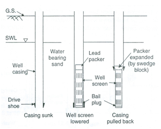
Fig. 19.1. Setting well screen using pull-back method.
(Source: Raghunath, 2007)
(ii) Open-Hole Method
In this method, the casing is first driven to a depth a little below the desired position for the top of the well screen. An open hole is then drilled in the sand below the casing and the casing is filled with the mud fluid (Fig. 19.2). The well screen is then lowered and the lead packer is swedged to the casing. This method is applicable to rotary-drilled wells.

Fig. 19.2. Setting well screen using open-hole method.
(Source: Raghunath, 2007)
(iii) Bail-Down Method
In this method, the casing is driven to the intended position of the top of the screen. A bail-down shoe with connection fittings is fitted to the bottom of the screen. A string of bailing pipe is screwed on to the coupling of the bail-down shoe and the screen is suspended on this string. The screen is then lowered inside the casing till it bailed out from below the screen (Fig. 19.3). The lead packer is provided and expanded with the swedge block to seal the casing and screen. This method is suitable for rotary drilled wells as well as for percussion drilled wells.
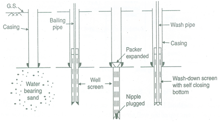
Fig. 19.3. Setting well screen using bail-down or wash-down method. (Source: Raghunath, 2007)
(iv) Wash-Down Method
In this method, the well casing is first set to the desired depth. A high velocity jet of drilling fluid is applied from a wash-down bottom, fitted to the end of the screen (Fig. 19.3). As a result, the sand is loosened and the screen is driven to the desired depth. Thereafter, water is circulated through the wash pipe to remove the drilling mud and the lead packer is expanded.
19.1.2 Grouting of Casing
Wells are grouted/cemented in the annular space surrounding the casing to prevent entry of polluted water, to protect the casing against the external corrosion and to stabilize caving rock formations. The grouting is achieved by using a cement grout between the outside of the casing and the inside of the drilled hole (Fig. 19.4). The grout is a mixture of cement and water of such a consistency that can be forced through the grout pipes and placed as needed.
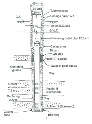
Fig. 19.4. Cementing/Grouting of the well casing (Shallow aquifer of inferior quality sealed and Aquifers II and III screened).
(Source: Raghunath, 2007)
The top of the casing should normally extend at least 50 cm above the level of the surrounding surface in such a way that it is isolated from direct contact with drainage wastes and sudden drainage discharges (Raghunath, 2007). The space around the casing should be grouted to a depth of about 6 m to seal the well from the entrance of surface drainage. A concrete platform should be constructed around the casing at the ground surface.
19.1.3 Gravel Packing
Gravel packing is done by placing an artificially packed gravel screen or envelope around the well screen. As mentioned in Lesson 16, the gravel pack has several advantages including the increase in well yield. A cross-section of a gravel-packed well is shown in Fig. 19.5.
Maximum grain size of a gravel pack should be nearly 1 cm, whereas the thickness should be in the range of 8 to 15 cm (Todd, 1980). The selected gravel should be washed and screened siliceous material that is rounded, abrasive-resistant and dense. Gravel should be placed in such a manner that it completely fills the annular space and minimizes segregation.
Gravel packing is generally done by placing two tremie pipes to the bottom of the well on opposite sides of the screen. Then the gravel is poured, washed, or pumped into the tremie pipes. The pipes are then pulled out of the well in stages
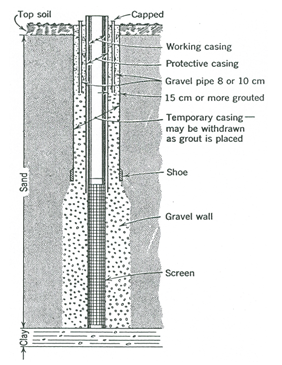
Fig. 19.5. Vertical cross-section of a gravel-packed well.
(Source: Todd, 1980)
as the pack is placed. In the cable-tool/percussion method of well drilling, the inner casing and screen are set inside the blank outer casing, the annular space is filled with gravel and then the outer casing is withdrawn out of the well. In sandy aquifers where a gravel pack is most essential, deep wells should be constructed by the rotary or reverse-circulation rotary method. The drilling fluid should be circulated and diluted with water before the gravel is introduced so as to avoid the clogging of the gravel pack.
19.2 Disinfection and Protection of Water Wells
19.2.1 Disinfection of Water Wells
After the completion of well installation, the pumping well and its appurtenances like the casing, pump, and pipe systems have to be disinfected or sterilized properly. Chlorinated water, prepared by dissolving dry calcium hypochlorite, liquid sodium hypochlorite or gaseous chlorine in water, is most effectively used for this purpose. The solution is poured into the well through the top of the casing, the water in the well is thoroughly agitated and allowed to stand for several hours. The well is then flushed to remove the entire disinfecting agent.
19.2.2 Protection of Water Wells
Proper sanitary precautions should be taken to protect the groundwater pumped from a well which is meant for human and animal consumption. Sources of pollution may exist either above or below the ground surface. Three commonly used protection measures for water wells are: (i) sanitary protection, (ii) frost protection, and (iii) abandonment of wells. These protection measures are succinctly described below.
(1) Sanitary Protection
The annular space between the outside of the casing and the inside of the drilled hole should be filled with cement grout in order to close avenues of access for undesirable water outside the casing. The top of the casing should be provided with a sanitary seal consisting of suitable packing glands that forms a water-tight seal between the pump column pipe and the well casing (Fig. 19.6). For pumps having an open-type base, a seal is required for the annular opening between the discharge pipe and the casing. The covers around the well should be made of concrete and should be elevated above the adjacent land level, and also should slope away from the well.
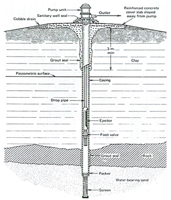
Fig. 19.6. A drilled well illustrating grout seal, concrete slab, and well seal for sanitary protection. (Source: Todd, 1980)
(2) Frost Protection
In the regions, affected by winter frost, the pumps and the water lines should be protected from freezing. The frost-proofing of a domestic well is performed by using a pitless adapter which is attached to the well casing and provides access to the well (Fig. 19.7). The discharge pipe runs about 2 m underground to the basement of the house (Todd, 1980).
(3) Abandonment of Wells
If the wells are of no use, i.e., they are abandoned, such wells must be sealed by filling them with clay, earth, or cement grout to prevent accidents, to avoid surface contaminants to enter the well and possible movement of polluted water from one aquifer to another as well as to conserve water in flowing wells.
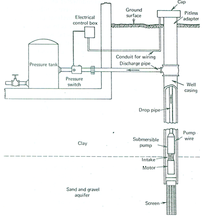
Fig. 19.7. Domestic well installation with a pitless adapter for protecting the well from frost. (Source: Todd, 1980)
19.3 Methods of Well Development
After the completion of a well, the new well is developed to increase its specific capacity (well discharge per unit drawdown), prevent sand pumping and obtain maximum economic well life. Well development is the process which causes reversals of flow through the screen openings so as to remove the finer material from the natural formations surrounding the perforated sections of the casing. As a result, the well provides clear (sand-free) water, thereby maximizing its specific capacity and well efficiency.
Various methods are available for developing a well, which include: (i) pumping, (ii) surging, (iii) use of compressed air, (iv) hydraulic jetting, (v) addition of chemicals/dispersing agents, (vi) hydraulic fracturing, (vii) backwashing, and (viii) use of explosives. These methods are briefly discussed below.
19.3.1 Pumping
This method of well development involves pumping a well in a series of steps from a low discharge to one exceeding the design capacity. At each step, the well is pumped until the water clears, after which the power is shut off and water in the pump column surges back into the well. The step is repeated until only clear water appears. The discharge rate is then increased and the procedure repeated until the final rate is the maximum capacity of the pump or well. This process agitates the fine material surrounding the well so that it can be carried into the well and pumped out. The courser fraction entering the well is removed by a bailer or sand pump from the well bottom.
19.3.2 Surging
In this method, a surge block attached to the bottom of a drill stem is repeatedly operated up and down in the well casing like a piston in a cylinder, thereby producing the required alternate reversals of flow. The procedure is completed when the loose materials accumulating in the bottom of the well become negligible. Further details of surging method can be found in Todd (1980) and Raghunath (2007).
19.3.3 Using Compressed Air
This method essentially involves both surging and pumping. During surging, a large volume of air is suddenly released and strong surge is produced by virtue of the resistance of water head, friction and inertia. Pumping is done using an ordinary air lift. The equipments required for well development by compressed air are: (a) air compressor capable of developing a maximum pressure of 700-1000 kN/m2 and capacity of providing about 6 liters of free air for each liter of water, (b) pumping pipeline and air line with suitable means of raising and lowering each other independently, and (c) accessories such as flexible high pressure hose, relief value, quick opening value, pressure gauge, etc. The arrangement of pumping pipeline and air line is shown in Fig. 19.8.
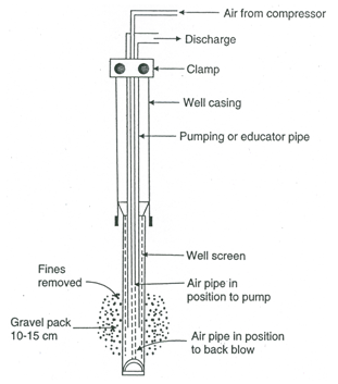
Fig. 19.8. Well development by compressed air.
(Source: Raghunath, 2007)
19.3.4 Hydraulic Jetting
In this method, a high velocity jet of water is applied horizontally through the screen openings with the tip of the nozzle at about 12-25 mm from the inner wall of the screen (Raghunath, 2007). A jetting tool coupled to the end of the pipe is lowered into the well. The top of the pipe is connected by a hose to a high pressure pump. As a pump is started, the jetting tool is slowly rotated and gradually raised or lowered so that the entire surface of the screen receives jetting action. The well is pumped by another pump to maintain the hydraulic gradient so that water and the loosened fine particles will keep entering the well. Hydraulic jetting is particularly effective in developing gravel-packed wells (Todd, 1980). However, this method is not suitable when a perforated pipe is used as a screen. The disadvantage of the hydraulic jetting method is that it requires considerable amount of water for effective operation.
19.3.5 Addition of Chemicals/Dispersing Agents
Sometimes, chemicals/dispersing agents are added during well development to disperse the clay particles in the mud cake or in the formation to avoid their sticking to sand grains and to speed up the well development process. Several polyphosphates are used for this purpose such as tetrasodium pyrophosphate, sodium tripolyphosphate, and sodium hexametaphosphate and sodium septaphosphate (Raghunath, 2007). Sometimes, blocks of solid carbon dioxide (dry ice) are added to a well after aciditizing and surging with compressed air. The accumulation of gaseous carbon dioxide released by sublimation creates a pressure within the well and upon release this causes a burst of muddy water from the well, thereby helping in well development.
For developing open-hole wells in limestone or dolomite formations, hydrochloric acid is added to water, which removes fine particles and widens fractures/fissures leading into the well bore (Todd, 1980).
19.3.6 Backwashing
The backwashing method provides a surging effect for well development and is widely used by well drillers. In this method, the top of the well is fitted with an air-tight cover. The backwashing system consists of a discharge pipe, a long air pipe, a short air pipe, and a three-way valve as shown in Fig. 19.9.
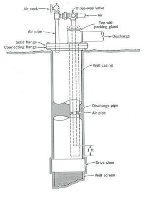
Fig. 19.9. Setup for well development by backwashing with air.
(Source: Todd, 1980)
Compressed air is released through the long air pipe, forcing air and water out of the well through the discharge pipe. After the water becomes clear, the air supply is stopped and the water is allowed to return to its static level. Thereafter, the three-way valve is turned to supply air into the top of the well through the short air pipe. This backwashes water from the well through the discharge pipe and at the same time agitates sand grains surrounding the well. Air is forced into the well until it starts escaping from the discharge pipe, after which the three-way valve is turned and the air supply is again directed down the long air pipe to pump the well. This procedure is repeated until the well is fully developed.
19.3.7 Hydraulic Fracturing
This technique is widely used in petroleum industry and it is occasionally employed for enhancing the yield of open-hole rock wells (Todd, 1980). In this method, a section of aquifer is isolated by inflatable packers on a pipe extending to the ground surface. After filling the pipe and isolated section with water, pump pressure is applied to fracture the rock. Sometimes, sand is pumped into the section to force the grains into the rock fractures in order to maintain the openings.
19.3.8 Using Explosives
Detonation of explosive in rock wells often increases yields by enlarging the borehole, increasing rock fractures, and removing fine-grained deposits on the face of the well bore. The method of well development using explosives is generally employed by experts, and hence its use is somewhat limited.
19.4 Well Maintenance and Rehabilitation
Although the expected service life of a well depends on the design, construction, development and operation of the well, proper maintenance of wells helps to improve their performance and increase their service life. Proper records of well discharge, drawdown, power consumption, operating hours, periodic checking of water quality and other such observations are very useful for formulating proper maintenance and rehabilitation plans.
19.4.1 Well Maintenance Criteria
In order to ensure that well performance does not deteriorate considerably, periodic test for well efficiency should be conducted and the results compared with the value obtained when the well was new. The well can be considered to be maintaining reasonable performance, if the well efficiency (ratio of theoretical drawdown to the measured drawdown in a pumping well) does not decline more than 15% from the original value (Roscoe Moss Company, 1990). When performance falls below an acceptable standard, redevelopment should be considered. As the monitoring of well efficiency is difficult and expensive, specific capacity (ratio of discharge to drawdown in a pumping well), which is a measure of the productivity of a pumping well, is often used to evaluate well performance with time. Seasonal and yearly influences on the pumping level must also be considered. The methodology for evaluating pumping wells can be found in Todd (1980), Raghunath (2007) and Roscoe Moss Company (1990).
19.4.2 Major Causes of Deteriorating Well Performance
The performance of wells can deteriorate because of one or combination of the following factors (Roscoe Moss Company, 1990):
(1) Change in hydrogeologic conditions, leading to declining groundwater levels.
(2) Excessive pumping of sand causing deterioration of the filter zone.
(3) Clogging of the filter zone by fine particles.
(4) Reduction in well discharge and well efficiency due to incrustation or bacterial growth in the well screen and/or filter zone.
(5) Degradation of water quality due to contamination.
(6) Structural damage of well casing and/or screen due to corrosion or other reasons.
19.4.3 Well Maintenance and Rehabilitation Techniques
Once the cause of deterioration in well performance is identified, one or more maintenance and rehabilitation techniques can be effective in restoring specific capacity and discharge of a pumping well or in protecting the well from further deterioration. Salient maintenance and rehabilitation techniques are as follows (Roscoe Moss Company, 1990):
(1) Redevelopment of the well using well development techniques.
(2) Chemical redevelopment of the well using acid or dispersing agents.
(3) Mechanical cleaning of the well screen by wire brushing or high-pressure jetting.
(4) Cleaning the screen with vibratory explosives.
(5) Structural repairs by setting liners, complete relining, or screen replacement.
(6) Reducing pumping rates, resetting the pump or deepening the well to offset decline in well production from lowering water tables.
References
Michael, A.M. and Khepar, S.D. (1999). Water Well and Pump Engineering. Tata McGraw-Hill Publishing Co. Ltd., New Delhi.
Raghunath, H.M. (2007). Ground Water. Third Edition, New Age International Publishers, New Delhi.
Roscoe Moss Company (1990). Handbook of Ground Water Development. John Wiley & Sons, New York.
Sarma, P.B.S. (2009). Groundwater Development and Management. Allied Publishers Pvt. Ltd., New Delhi.
Todd, D.K. (1980). Groundwater Hydrology. John Wiley & Sons, New York.
Suggested Readings
Todd, D.K. (1980). Groundwater Hydrology. John Wiley & Sons, New York.
Raghunath, H.M. (2007). Ground Water. Third Edition, New Age International Publishers, New Delhi.
Michael, A.M. and Khepar, S.D. (1999). Water Well and Pump Engineering. Tata McGraw-Hill Publishing Co. Ltd., New Delhi.
Sarma, P.B.S. (2009). Groundwater Development and Management. Allied Publishers Pvt. Ltd., New Delhi.
Last modified: Wednesday, 5 February 2014, 4:36 AM