Site pages
Current course
Participants
General
Module 1:Water Resources Utilization& Irrigati...
Module 2:Measurement of Irrigation Water
Module 3: Irrigation Water Conveyance Systems
Module 4: Land Grading Survey and Design
Module 5: Soil –Water – Atmosphere Plants Intera...
Module 6: Surface Irrigation Methods
Module 7: Pressurized Irrigation
Module 8: Economic Evaluation of Irrigation Projec...
Topic 9
LESSON 17 Land Grading Survey and Design
Land grading is the operation carried out to reshape the land by cutting, filling and smoothing to a designed continuous surface grade. The uniform grade is needed to control flow for irrigation and drainage purposes without soil erosion.A topographic map is a map that contains the information about the general topography of an area on the earth surface. The topographic map includes contours lines, location of natural features such as gullies, ditches and location of man-made features, such as buildings, roads, culverts, bridges etc. These are needed for detailed planning. Contour lines of the topographic map present the topography of an area. A contour line is an imaginary line that is obtained by joining the points of constant elevation on the surface of the ground. Fig. 17.1 depicts the different characteristics of contour lines.
A series of closed contours with higher values inside indicates a summit or hill and outside indicate a depression (Fig. 17.1 a & b). The contours lines form U-shaped curves and the higher values of contour inside the loop indicate a ridge line, V-shaped curves and the lower values of contour inside the loop indicate a valley line (Fig. 17.1 c & d). Contour lines cannot cross one another or merge on the map except in case of an overhanging cliff (Fig. 17.1 e & f). If several contour lines coincide the horizontal equivalent to zero then it indicates a vertical cliff. Four sets of contours (shown in Fig. 17.1g) shows a saddle a depression between summits. It is a dip in a ridge or the junction of two ridges. Line passing through the saddle and summits shows a watershed line.
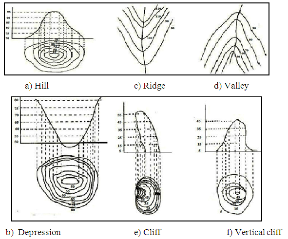
Fig. 17.1. Characteristics of contour lines. (Source: Mal, 1995)
After the topographic survey, proper estimation for cut and fill depths at different locations are prepared to obtain a suitable grade with a minimum volume of earthwork. The uniform grades allow fields to be laid out for irrigation runs of the proper length for border and ridges and furrows irrigation methods. Land grading is also beneficial in unirrigated areas to conserve moisture. In the process of land grading, the soil surface is formed to a predetermined grades so that each row or the surface slopes can also meet drainage requirement. This is accomplished by cutting, filling, and smoothing to a planned continuous surface grades with uniform slopes but not necessarily plane surfaces. In developing a land grading plan, filling depressions with soil from adjoining mounds and ridges and establishing grade in the direction of row grade, tillage or predominant natural slope is emphasized to minimize cuts and fills.
17.1 Land Levelling
Land levelling is the process of modifying the surface relief by grading and smoothing to a planned grade and to certain specifications required to facilitate or to improve the uniform application of water for irrigation and drainage purpose.
17.1.1 Criteria for Land Levelling
Criteria for land levelling depend on the soil profile conditions, land slope, climate, crops to be grown, methods of irrigation, and the farmers’ requirement. Land levelling should never be planned without knowing the soil-profile conditions and the maximum cut that can be made without seriously affecting agricultural production. Land levelling modifies the land surface for efficient surface irrigation. Irrigated land is also levelled to obtain good surface land drainage. The entire farm should be divided into smaller field subdivisions based on natural topographical boundaries in the initial plan itself, even though only a part of the farm may be levelled at the first instant. Each field subdivision may be further divided into relatively narrow strips on the approximate contour to reduce the slope of safe limits and avoid deep cuts of the surface soil. Each strip is a separate field for land levelling design. The irrigation and drainage systems for a particular field should be taken up simultaneously. The earth work (a cut) soil can be used as a fill (making embankment) for irrigation channel and cut soil area can be used for making channel.
a) Soil Profile Conditions
Soil profile study is desired before undertaking the levelling work. The soil profile map should depict details of soil texture of surface and subsurface soils. This should also include physical properties including infiltration rate, irrigation properties and the soil bulk density. The soil properties with reference to field capacity, wilting point and bulk density are required for deciding the duration of irrigation. The infiltration rate is required for deciding length of border & furrow and size of basins. Soil profile map should also provide the details of sand, depth of gravel, hard pans, rock or other material that might limit the depth of cut, as well as the extent of such areas. Soils with deep, well drained subsoils generally have little limitation on depth of cut. Cuts of 3 to 4 m can be made in soils with deep subsoils without permanently reducing potential crop production (Anderson et al., 1980). Deep cuts in shallow soils may expose inert materials which may not be desirable to grow crops. Addition of organic matter and fertilizers in soils can amend soil condition to grow crops without affecting crop productivity appreciably. Where deep cuts are unavoidable and the soil is shallow the harmful effects of top soil removal may be mitigated by scraping and storing the top soil, which is then replaced by the new grade after the movement of the subsoil material. Bench terracing in small strips minimises the harmful effects of severe top soil removal.
b) Land Slope
A good land grade is designed to achieve high irrigation efficiencies considering soil infiltration characteristics, irrigation stream size, the crops to be grown and erosion hazard from rainfall and degree of uniformity in water distribution. Sometimes excessive cuts are desired to eliminate cross slopes. To reduce the extent of cuts, the field is divided into parts and the levelling is done in strips at different elevations, separated by low ridges. This practice of grading is known as bench levelling. This type of levelling is especially required if there is considerable difference in elevation between adjacent strips. Earth work is done along the width of benches. The amount of earthwork is governed by the magnitude of the diagonal slope at right angles to the direction of irrigation. Safe limits of longitudinal slope of fields for different soil types are given in Table 17.1. (a).
Table 17.1. (a) Recommended safe limits of land slope for efficient irrigation
|
Type of soil |
Longitudinal slope % |
|
Heavy (clay) soils |
0.05 to 0.20 |
|
Medium (loamy) soils |
0.20 to 0.40 |
|
Light (sandy) soils |
0.25 to 0.65 |
(Source: Michael, 2010)
c) Cross Slope
Cross slope (slope perpendicular to longitudinal slope) is desired to reduce cut yardage or to establish the "plane of best fit." Cross slopes must be such that "breakthroughs" from both irrigation water and runoff from rainfall are held to a minimum. Recommended cross slopes for different furrow grades are presented in Table 17.2. (b).
Table 17.1. (b) Maximum recommended cross slope
|
Furrow Grade |
Cross Slope |
|
0.1 percent |
0.3 percent |
|
0.2 percent |
0.3 percent |
|
0.3 percent |
0.3 percent |
|
0.4 percent |
0.4 percent |
|
0.5 percent |
0.5 percent |
(Source: extension.missouri.edu/p/G1641)
d) Rainfall Characteristics
Rainfall characteristics viz. depth, duration and frequency influence the land drainage requirement or drainage coefficient. Land grading must meet the drainage requirements. Land grades should be non erosive so as to dispose excess rainfall at safer velocity without causing soil erosion.
e) Cropping Pattern
The high value crops with high labourer requirement along with their sensitivity to water stagnation justify the need for degree of levelling to reduce labour and production costs. Vegetables, oil seeds, pulses, medicinal plants justify a high levelling cost whereas a fodder crop or some cereal crops may need a much smaller investment as they tolerate some degree of water logging.
f) Irrigation Methods
Pressurized irrigation methods may not need high degree of land levelling, whereas surface irrigation needs proper land grading and levelling. When several methods of irrigation are to be used in the same field, the requirements of maximum length of run for surface irrigation methods should be worked out based on the soil texture.
Land Clearing
The land clearing includes removal of unwanted trees, brush, vegetation, trash and boulders from the area specified for land grading. The land clearing operation involves heavy earth moving machineries such as bulldozers, root rakes, stumpers, root cutters, rotary choppers and other appropriate machinery.
17.2 Levelling Layout of Field for Irrigation and Drainage Systems
The location of the field boundaries, irrigation water supply system, drains and farm roads and other physical features are required to be known prior to land levelling. The levelling plans should include estimate of volume of earth work for cut and fill. There should be proper ratio between excavations and fill. The plan should furnish information on soil, topography, and the requirement of the farmer. So that alternative field plan arrangements to accommodate desired changes. The planner should consider and visualise all possible layouts and the one best suited to the site should be selected considering water application methods, crops to be grown and the farmer’s choice. In making layout, planner should also consider location, size of drainage and irrigation ditches, pipelines location for water supply, easy access of movement of farm machineries to all fields, provision for combining smaller fields to larger fields and possibility of changing in cropping system.
Plans and Specifications
The field layout involves proper planning of field to arrange irrigation, drainage and roads for efficient irrigation and disposal of water.
a) Field Arrangement
Laying out fields of workable size and shape is important for successful irrigation farming. The fields are laid out as nearly rectangular as possible. Sharp turns in field boundaries should be avoided as far as possible in order to facilitate the use and movement of farm equipment. The field length is based on the maximum allowable length of run for the irrigation method selected. The field length may be equal to single run length or a multiple of the run lengths. Alternatively the field lengths may be limited by ownership boundaries. Table 17.2 provides the range of lengths for border strip and furrow methods of irrigation.
Table 17.2. Recommended length of run for border strip and furrow methods of irrigation
|
Soil type |
Length of run |
|
Sandy and sandy loam soils |
60 to 120 m |
|
Medium loam soils |
100 to 180 m |
|
Clay loam and clay soils |
150 to 300 m |
(Source: Michael, 2010)
Separation of fields will be desirable along the line of slope change. Sharp bends in otherwise nearly straight contours indicate change in the direction of maximum slope. Separation of fields at the bend is desirable for surface irrigation methods. Contour lines either close together or far apart may imply that the average natural slope is either too steep or too flat. Normally the lengths of fields are kept minimum to reduce the amount of cuts and fills required. Greater irregularity in spacing and direction of contours may show that the topography is non-uniform to the extent that it fails to show where a separation into fields can be made advantageously. Such areas are set apart to be graded individually as units. Excessively irregular or closely spaced contours indicate high cost of levelling.
b) Field Road System
Field road system is made to provide access to all areas of the farm for equipment, transportation of farm produce and operation of the irrigation system. Normally field roads are located at higher elevation than irrigation channels and followed below by field drains.
c) Drainage
Provision should be made to drain the excess rainfall promptly and safely. If the land is not naturally well drained, artificial drainage must be established along with installation of irrigation system. Seepage from over-irrigated areas at higher elevations and irrigation canals can damage lands in low-laying area. Interceptor drains may be necessary at the upper boundaries of the low-laying area to divert the seepage and prevent water logging. Integrated irrigation and drainage planning is often necessary for laying out a farm area for efficient water use.
17.3 Survey and Staking
a) Land Levelling Design
In order to carryout land levelling program topographic survey is performed.
The field is divided in the grids of equal sizes. Generally grids of 15 m×15 m or 30 m×30 m are used. The size of grid depends on degree of precision required. The grid points are located by establishing two or more base lines in each direction then to sight in the rest of the stakes. The elevations at each stakes are determined using the dumpy level. The normal procedure of survey is adopted for determination of elevation. Based on the observations of staff reading, the reduced levels of the grid points are estimated. The contour lines are drawn using the elevation values, and contour map is prepared. The field is graded as per requirement using contour map.
b) Procedure for Determination of Centroid of a Field
The field could be a rectangular, triangular or an irregular in shape. The centroid of a rectangular field is located at the point of intersection of its diagonals, whereas the intersection of the lines drawn from its corner to mid points of the opposite sides of triangle is the centroid of triangular field. In case of irregular field the area is divided into rectangles and right angled triangles for the determination of centroid. The centroid is located by computing moments from two reference lines at right angle to each other. The distance to the centroid of the field from any line of reference is equal to the sum of the products obtained by multiplying the area of each part times the distance from the line of reference to its centroid, divided by the total area of the field. By computing the distance to the centroid from two lines of reference perpendicular to each other, the exact point of centroid can be obtained.
The following example 17.1 illustrates the procedure to compute centroid of a field.
Example 17.1: Compute the elevation of centroid of a rectangular field. Stakes are to be kept to carry out levelling work of the field. The elevations at grid points as obtained from a topographic survey are stated below.
|
Elevation of stations at lines |
|||||
|
Stations |
1 |
2 |
3 |
4 |
5 |
|
A |
9.56 |
9.34 |
9.02 |
8.84 |
8.76 |
|
B |
8.37 |
8.24 |
8.98 |
8.68 |
8.57 |
|
C |
9.22 |
9.04 |
8.94 |
8.56 |
8.48 |
|
D |
8.92 |
8.84 |
8.76 |
8.31 |
8.02 |
Solution:
Sum of elevations of the 20 stations = 175.45 m
Total number of stations = 20
Elevation of centroid = 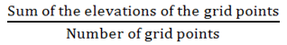
![]() m
m
References
Anderson, C. L., Halderman, A.D., Paul, H. A., and Rapp, E. (1980). Land Shaping Requirements. (In Design and Operation of Farm Irrigation Systems, Edited by Jensen, M.E), ASAE Monograph 3, St. Joseph, MI: 281-344.
Mal, B. C. (1995). Introduction to Soil and Water Conservation Engineering, Kalyani Publishers, New Delhi, India: 73-75.
Michael, A. M. (2010). Irrigation Theory and Practice, Vikas Publishing House PVT Ltd, Delhi, India: 383,385
Suggested Readings
Ali, M. H. (2011). Practices of Irrigation and On Farm Water Management Volume 2. Springer New York Dordrect Heidelberg London.
H. George, Hargreaves & P. Merkley Garg., (1998). Irrigation Fundamentals, Water Resource Publication, LIC, USA.
Mal, B.C. (1995) Introduction to Soil and Water Conservation Engineering. Kalyani Publishers, New Delhi, India.
Last modified: Saturday, 15 March 2014, 5:59 AM