Site pages
Current course
Participants
General
Module 1. Micro-irrigation
Module 2. Drip Irrigation System Design and Instal...
Module 3. Sprinkler Irrigation
Module 4. Fertigation System
Module 5. Quality Assurance & Economic Analysis
Module 6. Automation of Micro Irrigation System
Module 7. Greenhouse/Polyhouse Technology
Lesson 5. Components of Micro Irrigation System (MIS)
Micro irrigation systems components
Irrigation pipeline systems are generally described as branching systems. Various branches are given names such as main, submain, and lateral. Fig 5.1 shows a typical layout of micro-irrigation system. Choosing the right size main, submain, and lateral pipe to match the flow rates from the water source is important. Basic components include a pump and power unit, a backflow prevention device if chemicals are used with water, a filter, a water distribution system, and some devices for controlling the volume of water and pressure in the system. If the water source is from a city/municipal/rural water supply, a direct connection is possible.
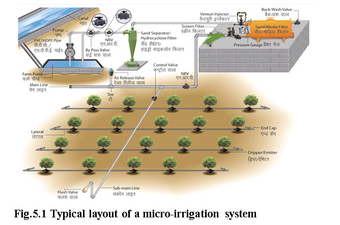
(Image source: http://74.52.53.155/sites/all/themes/ncpah/images/Drip_irrigation.jpg)
Pumps and power unit
Micro-irrigation systems are typically designed to make the best use of the amount of water available. The type and size of pump selected will depend on the amount of water required, the desired pressure and the location of the pump relative to the distribution network. Electric power units or internal combustion engine driven pumps are equally adaptable. However, the electric power unit is preferred because it is easier to automate.
Filters
Filters remove sand and larger suspended particles before they enter the distribution network. However, the filters cannot remove dissolved minerals, bacteria and some algae. The three types generally used are screen, disk and sand filters.
Distribution lines
The water distribution system is a network of pipes and tubes that can range in size from 1/2 inch to 6 inches (12 mm to 150 mm) in diameter. Water from the pump may be carried to the edge of the field by a single large main. Smaller submains may then carry the water to laterals and ultimately to the emitters.
5.1 Control Head
The head control unit of micro-irrigation system includes the following components.
1. Pump/Overhead tank: It is required to provide sufficient pressure in the system. Centrifugal pumps are generally used for low pressure trickle systems. Overhead tanks can be used for small areas or orchard crops with comparatively lesser water requirements.
2. Fertilizer applicator: Application of fertilizer into pressurized irrigation system is done by either a by-pass pressure tank, or by venturi injector or direct injection system.
3. Filters: The hazard of blocking or clogging necessitates the use of filters for efficient and trouble free operation of the micro-irrigation system. The different types of filters used in micro-irrigation system are described below.
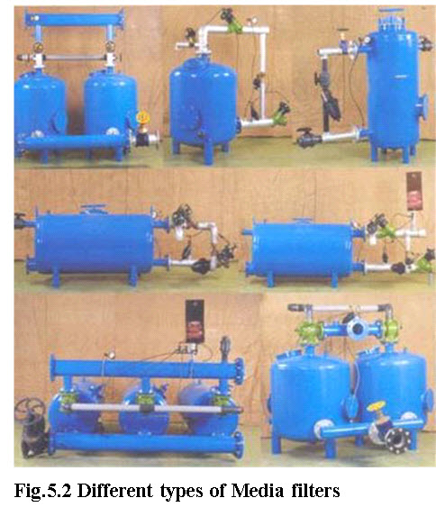
a) Gravel or Media filter: Media filters consist of fine gravel or coarse quartz sand, of selected sizes (usually 1.5 – 4 mm in diameter) free of calcium carbonate placed in a cylindrical tank. These filters are effective in removing light suspended materials, such as algae and other organic materials, fine sand and silt particles. This type of filtration is essential for primary filtration of irrigation water from open water reservoirs, canals or reservoirs in which algae may develop. Water is introduced at the top, while a layer of coarse gravel is put near the outlet bottom. Reversing the direction of flow and opening the water drainage valve cleans the filter. Pressure gauges are placed at the inlet and at the outlet ends of the filter to measure the head loss across the filter. If the head loss exceeds more than 30 kPa, filter needs back washing. Different types of media filters are shown through Fig. 5.2
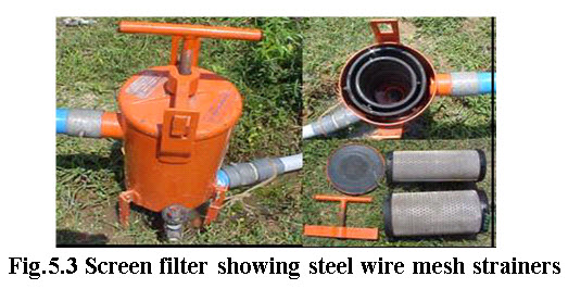
b) Screen filters: Screen filters are always installed for final filtration as an additional safeguard against clogging. While majority of impurities are filtered by sand filter, minute sand particles and other small impurities pass through it. The screen filter, containing screen strainer, which filters physical impurities and allows only clean water to enter into the micro-irrigation system. The screens are usually cylindrical and made of non-corrosive metal or plastic material. Steel wire mesh filter is shown in Fig. 5.3 These are available in a wide variety of types and flow rate capacities with screen sizes ranging from 20 mesh to 200 mesh. The aperture size of the screen opening should be between one seventh and one tenth of the orifice size of emission devices used.
(Image source: Report of the task report on Micro-irrigation, Ministry of Agriculture, Dept. of Agriculture & cooperation, Govt. of India, New Delhi, Jan, 2004)
c) Centrifugal filters: Centrifugal filters are effective in filtering sand, fine gravel and other high density materials from well or river water. Water is introduced tangentially at the top of a cone and creates a circular motion resulting in a centrifugal force, which throws the heavy suspended particles against the walls. The separated particles are collected in the narrow collecting vessel at the bottom (Fig. 5.4).
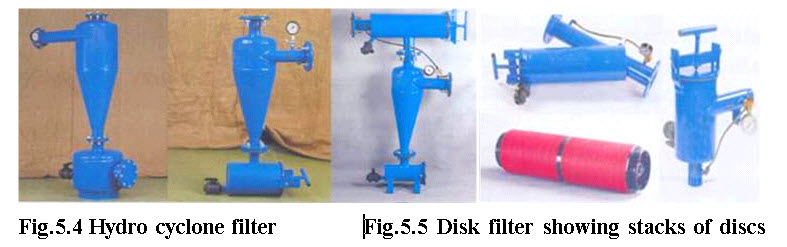
(Image source: Report of the task report on Micro-irrigation, Ministry of agriculture, Dept. of Agriculture & cooperation, Govt. of India, New Delhi, Jan, 2004)
d) Disk filters: Disk filter contains stacks of grooved, ring shaped disks that capture debris and are very effective in the filtration of organic material and algae. Fig. 5.5 shows disk filters. During the filtration mode, the disks are pressed together. There is an angle in the alignment of two adjacent disks, resulting in cavities of varying size and partly turbulent flow. The sizes of the groove determine the filtration grade. Disk filters are available in a wide size range (25-400 microns). Back flushing can clean disk filters. However they require back flushing pressure as high as 2 to 3 kg/cm2.
4. Pressure relief valves, regulators or bye pass arrangement: These valves may be installed at any point where possibility exists for excessively high pressures, either static or surge pressures to occur. A bye pass arrangement is simplest and cost effective means to avoid problems of high pressures instead of using costly pressure relief valves.
5. Check valves or non-return valves: These valves are used to prevent unwanted flow reversal. They are used to prevent damaging back flow from the system to avoid return flow of chemicals and fertilizers from the system into the water source itself to avoid contamination of water source.
Chemical injection equipment
Micro-irrigation’s high distribution uniformity gives it great potential for uniformly and efficiently applying agricultural chemicals, a process called chemigation. The main components of a chemigation unit are a chemical solution tank, an injection system and chemigation safety devices.
Chemical Solution Tanks
Chemical solution tanks generally are constructed of poly or fibreglass. A conical form at the tank bottom facilitates flushing it completely so that no material is wasted. Tanks should have an easy-clean screen downstream of the valve to make them easier to clean.
Injection system
The main types of chemical injectors are the venturi injector, injection pump, and the differential tank. The different types of fertilizer / chemical injection system are shown through Fig. 5.6. Criteria for selecting the proper injection system include cost, ease of use/repair, durability and susceptibility to corrosion.
With venturi injectors, water is extracted from the main line, then (1) pressure is added with a centrifugal pump or (2) a pressure differential is created by a valve in the mainline forcing water through the injector at high velocity. The high-velocity water passing through the throat of the venturi creates a vacuum or negative pressure, generating suction to draw chemicals into the injector from the chemical tank. Although the venturi is cheaper than a positive displacement pump, its injection rate is more difficult to control.
With injection pumps, water is pumped into the system using pistons, diaphragms or gears. An injection pump has a small motor powered either by electricity or by energy from the water itself. The motor moves small pumps (diaphragms) or pistons to inject fertilizer into the system. The advantage of injection pumps is that chemicals can be injected with high uniformity at rates easily be adjusted regardless of discharge pressure.
With differential tanks, water is forced through a tank containing the chemical to be injected. As water passes into the tank, fertilizer is injected into the irrigation system. One disadvantage of such a system is that the concentration of the chemical in the tank decreases over time.
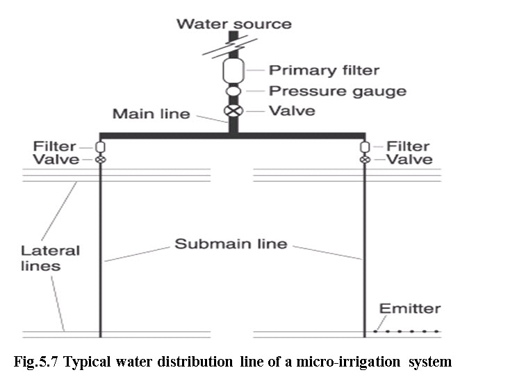
5.2 Water Distribution Network
The water distribution network constitutes main line, submains line and laterals with drippers and other accessories (Fig. 5.7).
5.2.1. Mainline
he mainline transports water within the field and distribute to submains. Mainline is made of rigid PVC or High Density Polyethylene (HDPE). Pipelines of 65 mm diameter and above with a pressure rating 4 to 6 kg/cm2 are used for main line pipes.
5.2.2. Submains
Submains distribute water evenly to a number of lateral lines. For sub main pipes, rigid PVC, HDPE or LDPE (Low Density Polyethylene) of diameter ranging from 32 mm to 75 mm having pressure rating of 2.5 kg/cm2 are used.
5.2.3. Laterals
Laterals distribute the water uniformly along their length by means of drippers or emitters. These are normally manufactured from LDPE and LLDPE (Fig.5.8). Generally pipes having 10, 12 and 16 mm internal diameter with wall thickness varying from 1 to 3 mm are used as laterals.

(Source: Enciso, J. and Porter, D. Basics of Micro-irrigation. Texas Cooperative Extension, The Texas A & M University System)
 (Source: www.ag.ndsu.edu/pubs/ageng/irrigate/ae1243w.htm 16th Aug, 2012.)
5.3 Emission Devices
The actual application of water in a micro- irrigation system is through an emitter. The emitter is a metering device made from plastic that delivers a small but precise discharge. The quantity of water delivered from these emitters is usually expressed in liters per hour (Lh-1). These emitters dissipate water pressure through the use of long-paths, small orifices or diaphragms. Some emitters are pressure compensating meaning they discharge water at a constant rate over a range of pressures. Emission devices deliver water in three different modes: drip, bubbler and micro-sprinkler. In drip mode, water is applied as droplets or trickles. In bubbler mode, water `bubbles out' from the emitters. Water is sprinkled, sprayed, or misted in the micro-sprinkler mode. Emitters for each of these modes are available in several discharge increments. Some emitters are adapted to apply water to closely spaced crops planted in rows. Other emitters are used to irrigate several plants at once. There are emitters that apply water to a single plant.
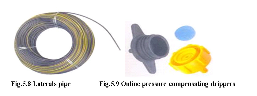
Fig.5.10 Online non-pressure compensating drippers
(Image source: Report of the Task Force on Micro-irrigation, Ministry of Agriculture, Dept. of Agriculture & cooperation, Govt. of India, New Delhi, Jan, 2004)
Emitters / Drippers
They function as energy dissipaters, reducing the inlet pressure head (0.5 to 1.5 atmospheres) to zero atmospheres at the outlet. The commonly used drippers are online pressure compensating or online non-pressure compensating, in-line dripper, adjustable discharge type drippers, vortex type drippers and micro tubing of 1 to 4 mm diameter. These are manufactured from Poly- propylene or LLDPE.
A) Online pressure compensating drippers: A pressure compensating type dripper supplies water uniformly on long rows and on uneven slopes. These are manufactured with high quality flexible rubber diaphragm or disc inside the emitter that it changes shape according to operating pressure and delivers uniform discharge (Fig. 5.9). These are most suitable on slopes and difficult topographic terrains.
B) Online non-pressure compensating drippers: In such type of drippers discharge tends to vary with operating pressure. They have simple thread type, labyrinth type, zigzag path, vortex type flow path or have float type arrangement to dissipate energy. However they are cheap and available in affordable price. Different types on line non-pressure compensating types of drippers are shown through Fig. 5.10.
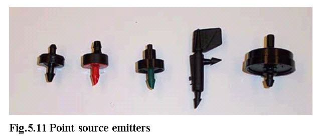
Point source emitters
Point source emitters are typically installed on the outside of the distribution line. Point source emitters dissipate water pressure through a long narrow path and a vortex chamber or a small orifice before discharging into the air (Fig. 5.11). The emitters can take a predetermined water pressure at its inlet and reduce it to almost zero as the water exits. Some can be taken apart and manually cleaned. The typical flow rates range from 2 to 8 Lh-1.
(Image source: http://fvtchort.wikispaces.com/Soils+Group+1)
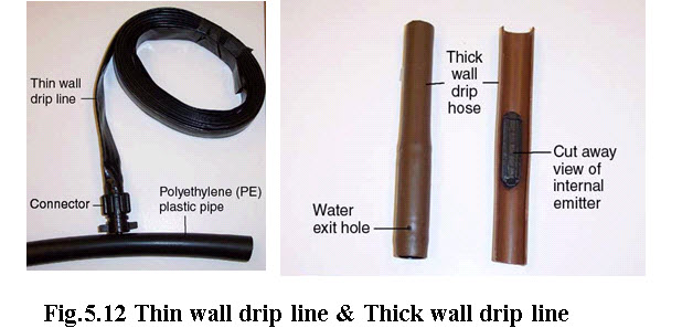
Line source emitter
Line source emitters are suitable for closely spaced row crops in fields and gardens. Line source emitters are available in two variations:
-
Thin wall drip line
-
Thick wall drip hose.
A thin walled drip line has internal emitters molded or glued together at set distances within a thin plastic distribution line (Fig. 5.12). The drip line is available in a wide range of diameters, wall thickness, and emitter spacing and flow rates. The emitter spacing is selected to closely fit plant spacing for most row crops. The flow rate is typically expressed in gallons per minute (gpm) along a 100-foot section. Drip lines are either buried below the ground or laid on the surface. Burial of the drip line is preferred to avoid degradation from heat and ultraviolet rays and displacement from strong winds. However, some specialized equipment to install and extract the thin drip distribution line is required.
 (Image source: http://fvtchort.wikispaces.com/Soils+Group+1)
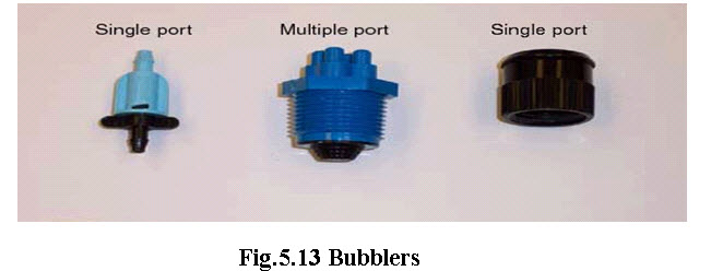
Bubblers
Bubblers typically apply water on a "per plant" basis. Bubblers are very similar to the point source external emitters in shape but differ in performance (Fig. 5.13). Water from the bubbler head either runs down from the emission device or spreads a few inches in an umbrella pattern. The bubbler emitters dissipate water pressure through a variety of diaphragm materials and deflect water through small orifices. Most bubbler emitters are marketed as pressure compensating. The bubblers are equipped with single or multiple port outlets. Most bubbler heads are used in planter boxes, tree wells, or specialized landscape applications where deep localized watering is preferred. The typical flow rate from bubbler emitters varies between 8 and 75 Lh-1.
Micro sprinklers
Micro-sprinklers are emitters commonly known as sprinkler or spray heads (Fig. 5.14). These are of several types. The emitters operate by throwing water through in air, usually in predetermined patterns. Depending on the water throw patterns, the micro-sprinklers are referred to as mini-sprays, micro-sprays, jets, or spinners. The sprinkler heads are external emitters individually connected to the lateral pipe typically using "spaghetti tubing," which is very small (1/8 inch to 1/4 inch) diameter tubing. The sprinkler heads can be mounted on a support stake or connected to the supply pipe. Micro-sprinklers are desirable because fewer sprinkler heads are necessary to cover larger areas. The flow rates of micro-sprinkler emitters vary from 16 lph to 180 lph depending on the orifice size and line pressure
(Image source: http://fvtchort.wikispaces.com/Soils+Group+1)
Emission devices selection
The selection of emission devices involves choosing the type of device to be used and then determining the capacity of the device. The type of emission device depends on such factors as the crop to be irrigated, filtration requirements, the need for a cover crop and/or frost protection, cost and grower preference. Micro sprinklers should be strongly considered when a cover crop is needed for erosion, pest or disease control or when frost protection is desired. Line-source emitters are especially well suited for row crops, although closely spaced point-source emitters, bubblers and micro sprinklers can also be used. In situations where filtration requirements are high, bubblers and micro sprinklers may be the most viable alternatives.
References :
-
Anonymous (2004). Report of the Task Force on Micro-irrigation, Ministry of Agriculture, Dept. of Agriculture & cooperation, Govt. of India, New Delhi, Jan, 2004)
-
www.ag.ndsu.edu/pubs/ageng/irrigate/ae1243w.htm 16th Aug, 2012.
Suggested Reading:
-
James, L. G. (1988). Principles of Farm Irrigation System Design, John Willey & Sons, Inc. New York.
-
Tiwari, K.N. (2007). Pressurized Irrigation, Scientific Publication No. PFDC/IITKGP/1/2007, Precision Farming Development (NCPAH), IIT Kharagpur, India.
Last modified: Friday, 17 January 2014, 6:04 AM