Site pages
Current course
Participants
General
Module 1: Introduction and Concept of Soil Erosion
Module 2: Water Erosion and Control
Module 3: Wind Erosion, Estimation and Control
Module 4: Soil Loss- Sediment Yield Estimation
Module 5: Sedimentation
Module 6: Topographic Survey and Contour Maps
Module 7: Land Use Capability Classification
Module 8: Grassed Waterways
Module 9: Water Harvesting
Module 10: Water Quality and Pollution
Module 11: Watershed Modeling
Keywords
Lesson 23 Land Survey and Contour Maps
The purpose of topographic survey is to get the necessary data to produce a topographic map of the earth’s surface. This map will include contour lines, location of natural features, such as streams, gullies, and ditches and man-made features like bridges, culverts, roads, fences, etc. which are essential for detailed planning. The best practical method of presenting topography is by means of land surveys and contour maps.
23.1 Survey of Land
Land surveying is the science and art of making all essential measurements to determine the relative position of points or physical and cultural details above, on, or beneath the surface of the earth and to depict them in a usable form, or to establish the position of points or details. These points are usually on the surface of the earth and they are often used to establish land maps and boundaries for ownership or governmental purposes. Furthermore, it is the detailed study or inspection by gathering information through observations, measurements in the field, questionnaires, or research of legal instruments and data analysis for the purpose of planning, designing, and establishing property boundaries. It involves the re-establishment of cadastral surveys and land boundaries based on documents of record and historical evidence, as well as certifying surveys (as required by statute or local ordinance) of subdivision plans/maps, registered land surveys, judicial surveys and space delineation.
Land surveying can include associated services such as mapping, related data accumulation, construction layout surveys, precision measurements of length, angle, elevation, area, volume, as well as horizontal and vertical control surveys. It also includes the analysis and utilization of land survey data. Surveying has been an essential element in the development of the human environment since the beginning of recorded history (about 5,000 years ago). It is required in the planning and execution of nearly every form of construction. It’s most familiar modern uses are in the fields of transport, building and construction, communications, mapping and the definition of legal boundaries for land ownership.
The earliest surveys were performed only for the purpose of recording the boundaries of plots of land. Due to advancements in technology, the science of surveying has also attained its due importance. In the absence of accurate maps, it is impossible to lay out the alignment of roads, railways, canals, tunnels, transmission, power lines, and microwave or television relaying towers. Detailed maps of the sites of engineering projects are necessary for the precise installation of sophisticated plants and machineries. Surveying is the first step for the execution of any such project.
23.2 Types of Maps and Mapping Units
The following types of maps are used in land surveying.
Plan: A plan is a graphical representation of the features on the earth surface or below the earth surface as projected on a horizontal plane. This may not necessarily show its graphical position on the globe. On a plan, horizontal distances and directions are generally shown.
Map: The representation of the earth surface on a small scale is called a map. The map must show its geographical position on the globe with the help of latitude and longitude. On a map the topography of the terrain, is depicted generally by contours, hachures and spot levels.
Topographical Map: The maps which are on sufficiently large scale to enable the individual features shown on the map to be identified on the ground by their shapes and positions, are called topographical maps.
Geographical Maps: The maps which are on such a small scale that the features shown on the map are suitably generalised and give a picture of the country as a whole and not a strict representation of its individual features, are called Geographical maps.
Two kinds of measurements are used in plane surveying;
Linear Measurement, i.e. Horizontal or Vertical Distance
Angular Measurement, i.e. Horizontal or Vertical Angles.
i) Linear Measures: According to the standards of Weight and Measure Act (India) 1956, the metric system has been introduced in India. Before 1956, F.P.S (Foot, pound, second) system was used for the measurements. For measurements of distances, metre and centimetre have been recommended as standard units.
|
Basic units of length in metric system: |
10 millimetres = 1 centimetre 10 centimetres = 1 decimetre 10 decimetre = 1 metre 10 metres = 1 decametre 10 decametres = 1 hectametre 10 hectametres = 1 kilometres 1.852 kilometres = 1 nautical mile |
|
Basic units of area in metric system |
100 sq. metres = 1 are 10 ares = 1 deka-are 10 deca ares = 1 hecta-are |
|
Basic units of volume in metric system |
1000 cub. millimetres = 1 cub. centimetre 1000 cub. centimetres = 1 cub. decimetre 1000 cub. decimetres = 1 cub. metre |
|
Basic units of length in FPS system |
12 inches = 1 foot 3 feet = 1 yard 5.5 yards = 1 rod, pole, or 1 sq. perch 4 poles = 1 chain (66 feet) 10 chains = 1 furlong 8 furlong = 1 mile 6 feet = 1 fathom 120 fathoms = 1 cable length 6080 feet = 1 nautical mile |
|
Basic units of volume in FPS system |
1728 cu. inches = 1 cu. Foot 27 cu. Feet = 1 cu. Yard |
Conversion Factor for Lengths
|
Metres |
Yards |
Feet |
Inches |
|
1 |
1.0936 |
3.2808 |
39.37 |
|
0.9144 |
1 |
3 |
36 |
|
0.3048 |
0.3333 |
1 |
12 |
|
0.0254 |
0.0278 |
0.0833 |
1 |
Conversion Factor for Areas
|
Sq. metres |
Sq. yards |
Sq. feet |
Sq. inches |
|
1 |
1.196 |
10.7639 |
1550 |
|
0.8361 |
1 |
9 |
1296 |
|
0.0929 |
0.1111 |
1 |
144 |
|
0.00065 |
0.00077 |
0.0069 |
1 |
Conversion Factor for Areas
|
Ares |
Acres |
Sq. metres |
Sq. yards |
|
1 |
0.0247 |
100 |
119.6 |
|
40.496 |
1 |
4046.9 |
4840 |
|
0.01 |
0.000247 |
1 |
1.196 |
|
0.0084 |
0.00021 |
0.8361 |
1 |
Conversion Factor for Volumes
|
Cub. metres |
Cub. yards |
Gallons (Imps) |
|
1 |
1.308 |
219.969 |
|
0.7645 |
1 |
168.178 |
|
0.00455 |
0.00595 |
1 |
Source:
ii) Angular Measures: Angles may be defined as the difference in the direction of two intersecting lines; it is the inclination of two straight lines. The unit of a plane angle is ‘radian’. Angle is defined as the measure between two radii of a circle which contain an arc equal to the radius of the circle. The popular system of angular measurements, are:
Sexagesimal System of Angular Measurements:
In this system the circumference of a circle, is divided into 360 equal parts, each part is known as one degree. 1/60th part of a degree is called a minute and 1/60th part of a minute, is called a second. i.e.
1 circumference = 360 degree of arc
1° = 60 minutes of arc
1 minute = 60 seconds of arc
Centesimal System of Angular Measurements:
In this system circumference of a circle is divided into 400 equal parts, each part is known as grad. One hundredth part of a grad is known as centigrad and one hundredth part of a centigrad is known centi-centigrad. i.e.
1 circumference = 400 grads
1 grad = 100 centigrads
1 centigrad = 100 centi-centigrads
From the ancient times, sexagesimal system is being widely used in different countries of the world. Most complete mathematical tables are available in this system and most surveying instruments i.e. theodolites, sextants etc. are graduated according to this system. Due to increased facility in computation and interpolation, the centesimal system for angular measurements is gaining popularity in the western countries these days.
Conversion Factors from One System to Other
|
Degrees |
Grads |
Minutes |
Centigrads |
Seconds |
Centi-centigrads |
|
1 |
1.1111 |
60 |
111.11 |
3600 |
11111 |
|
0.9 |
1 |
54 |
100 |
3240 |
10000 |
|
0.0167 |
0.01852 |
1 |
1.8518 |
60 |
185.18 |
|
0.0090 |
0.0100 |
0.5405 |
1 |
32.4 |
100 |
|
0.00027 |
0.0003 |
0.0167 |
0.0309 |
1 |
3.0864 |
|
0.00009 |
0.0001 |
0.0054 |
0.0100 |
0.324 |
1 |
23.3 Methods of Land Survey
The surveying may be primarily divided into two divisions.
Surveying
Geodetic Surveying
23.3.1 Plane Surveying: The survey in which the earth surface is assumed as a plane and the curvature of the earth is ignored is known as plane survey. In plane surveying, every elevation measurement has a small amount of error; however, plane surveying is easier to complete and provides sufficient accuracy for smaller areas. As plane survey extends only up to small areas, the lines connecting any two points on the surface of the earth, are treated as straight lines and the angles between these lines are taken as plane angles. Surveys covering an area up to 260 km2 may be treated as plane surveys because the difference in length between the arc and its subtended chord on the earth surface for a distance of 18.2 km is only 0.1 m. Plane surveying is used for the layout of highway, railways, projects, canals, fixing boundaries, pillars, construction of bridges, factories etc. For proper, economical and accurate planning of projects, plane survey is needed and its practical significance cannot be overestimated.
23.3.2 Geodetic Surveying: The art of surveying the earth surface considering its shape and size (curvature) is called geodetic surveying. Geodetic surveying is suitable for finding out the area of any region on the earth surface, the length and directions of the border lines, contour lines and location of basic points. It is assumed that the shape of earth is spheroid. The convention held by the International Geodetic and Geophysical Union in 1924 assumed 41,852,960 ft as the earth's diameter at the equator and at the poles the diameter is 41,711,940 ft. Thus, measurement of distances is taken along curved surfaces and not along straight lines. The latitudes and longitudes are determined considering the spheroidical shape of the earth. The points which are used to find out the shape, size and coordinates of the earth surface is called geodetic datum. In India, geodetic surveys are conducted by the department of the Survey of India under the direction of the Surveyor General of India.
Different kinds of surveys are taken up depending on the nature of the field and purpose of the survey. These include topographic surveys, cadastral surveys, city surveys, hydrographic surveys, astronomical surveys, engineering surveys, military or defense surveys, mine surveys, geographical surveys, archaeological surveys etc. Based on the instruments used surveys may also be classified as chain surveying, compass surveying, plane table surveying, theodolite surveying, tachometric surveying, triangulation surveying, aerial surveying and photogrammetric surveying.
Basic surveying measurements include the following eight aspects
1. Determining Horizontal Position: The horizontal position of points is usually determined using traversing, triangulation, trilateration or grid referencing methods.
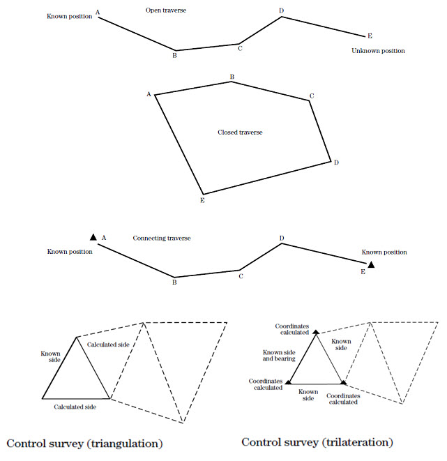
Fig. 23.1. Methods for Measuring Horizontal Position.
(Source: Natural Resources Conservation Service, 2008)
2. Determining Horizontal Distance: Measurement of horizontal distances can be accomplished by a number of methods including pacing, taping, stadia, and electronic distance measuring devices. The choice of measurement device usually is determined by the accuracy required.
3. Determining Horizontal Angles: The direction of any line on a course is determined by the reference angle in the horizontal plane to the previous line on the course. Three types of reference angles; interior angles, exterior angles, deflection angles.
4. Determining Direction: Course direction is expressed by the bearing of a particular leg of the course. When there is a change in course direction, a new bearing can be calculated given the bearing of the first course direction and the angle of the change in course direction.
5. Determining Vertical Position: The vertical position of points is determined from a series of level readings. Level surveys are referenced to a datum. Mean sea level usually is used as a standard datum; however, an assumed datum may be used for minor surveys. Vertical distances above and below a datum are called elevations. Vertical distance is measured as the elevation difference between any two points with reference to a datum.
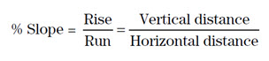
6. Determining Vertical Distance: Vertical distance is one side of a right triangle and is calculated by the relationship –
7. Determining Vertical Angles: Vertical angles can be expressed either as a true vertical angle or as a zenith angle. A true vertical angle is an angle measured from the horizontal either upward or downward. Vertical angles measured upwards from the horizontal are positive angles and those measured downward are negative angles. Zenith angles are measured downward from a vertical plumb line above the point. The zenith angle is measured from 0 degrees directly above and is equal to 90 degrees minus the vertical angle.
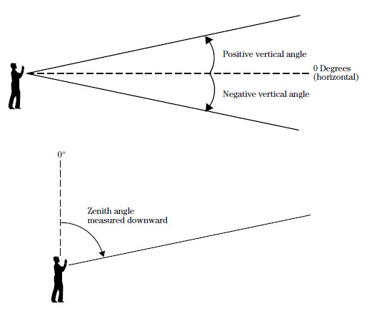
Fig. 23.2. Methods for Measuring Vertical Angles.
(Source: Natural Resources Conservation Service, 2008)
8. Determining Vertical Coordinate Position: Vertical coordinate position is also known as the elevation of the point and is determined by adding or subtracting the vertical difference between a known point and the position being calculated to the elevation of the known point.
23.4 Contour Maps Preparation
An imaginary line on the ground, joining the points of equal elevation above the assumed datum is called a contour line. It is a plan projection of the plane passing through the points of equal elevation on the surface of the earth. Concept of a contour can be made clear by surveying the boundary of still water in a pond. If the level of the water surface is 100 m, then the periphery of water represents a contour line of 100 m. If the water level is reduced by 5 metres, the new periphery of water will then represent a contour of 95 m. The following characteristics of contours are kept in view while preparing or reading a contour map.
Two contours of equal elevation do not cross each other except in the case of an over-hanging cliff.
Contours of different elevations do not unite to form one contour except in the case of a vertical cliff.
Contours lines located close to each other indicate a steep slope and those located far apart represent a gentle slope.
Contours equally spaced depict a uniform slope. Parallel, equidistant and straight contours lines represent an inclined plane surface.
Contours at any point are perpendicular to the line of the steepest slope at the point.
A contour line must close itself but need to be necessarily within the limits of the map itself.
Ring contours with higher values inside depict a hill whereas a set of ring contours with lower values inside represent a pond or a depression without an outlet.
When contours cross a ridge or V-shaped valley, they form sharp V-shapes across them. Contours represent a ridge line, if the concavity of higher value contours lies towards the next lower value contour and a valley if the concavity of the lower value contours lies towards the higher value contour.
The same contour must appear on both the sides of a ridge or a valley.
Contours do not have sharp turnings.
Field work for locating contours may be in various ways according to the instruments used. The various methods of locating contours may be divided into two main classes:
Direct Method
Indirect Method
i) Direct Method: In the direct method, the contour to be plotted is actually traced on the ground. Points which happen to fall on a desired contour are only surveyed, plotted and finally joined to obtain the particular contour. This method is slow and tedious and thus used for large scale maps, small contour interval and high degree of precision. A temporary benchmark is established near the area to be surveyed with reference to a permanent bench mark. The level is then set up in such a position so that the maximum number of points can be commanded from the instrument station. The height of instrument is determined by taking a back sight on the benchmark and adding it to the reference level of bench mark. The staff reading required to fix points on the various contours is determined by subtracting the Reduced Level (R.L.) of each of the contours from the height of instrument.
ii) Indirect Method: In practice, generally indirect method is used. In this method sufficient numbers of points are given spot levels. The location of such points can be conveniently plotted on a plane table section as these generally form the corners of the well, shaped geometrical figures i.e. squares, rectangles, triangles, etc. It is seldom possible to have exact spot level of any point on exact value of the contour. The spot level of the important features which represent hill tops, ridge lines, bed of streams and lowest points of the depression are also taken, to depict their correct features while drawing contour lines. The contours in between spot levels are interpolated and drawn. This method of contouring is sometimes known as contouring by spot levels. Indirect method of contouring is commonly employed in small scale surveys of extensive areas. This method is cheaper, quicker and less tedious as compared to the direct method of contouring.
23.5 Uses of Contour Maps in SWCE
Keeping in view, the characteristics of contours enumerated above, different natural features may be shown by contours. Followings are some of the important uses:
To study the general character of the tract of the country without visiting the ground. With the knowledge of the characteristic of the contours, it is easier to visualise whether the country is flat, undulating or mountainous.
To decide the most economical and suitable sites of re-engineering for engineering works such as canals, sewers, reservoirs, roads, railways etc.
To determine the catchment area of the drainage basin and hence the capacity of the proposed reservoir.
To compute the earth work required for filling or cutting along the linear alignment of projects such as canals, roads, etc.
Site selection and dimensioning of soil and water conservation measures like contour bunds, contour trenches etc.
Keywords: Plan, Plane Surveying, Geodetic Surveying, Contour Maps
References
Natural Resources Conservation Service (2008) Surveying. Engineering Field Handbook. United States Department of Agriculture
Suggested Readings
Agor, R. (1979) A Text Book of Surveying and Leveling. Survey of India. Delhi
Venkatramaiah, C. (1996). Textbook of Surveying. Universities Press.
Natural Resources Conservation Service (2008) Surveying. Engineering Field Handbook. United States Department of Agriculture
Last modified: Monday, 23 December 2013, 9:24 AM