Site pages
Current course
Participants
General
Module 1: Introduction and Concept of Soil Erosion
Module 2: Water Erosion and Control
Module 3: Wind Erosion, Estimation and Control
Module 4: Soil Loss- Sediment Yield Estimation
Module 5: Sedimentation
Module 6: Topographic Survey and Contour Maps
Module 7: Land Use Capability Classification
Module 8: Grassed Waterways
Module 9: Water Harvesting
Module 10: Water Quality and Pollution
Module 11: Watershed Modeling
Keywords
Lesson 24 Leveling and Grading of Land
Land leveling is the process of modifying the surface relief by smoothening it. It is the process of flattening or modifying existing (natural) slopes or undulations and thereby creating a level surface. Normally land leveling requires excavation and movement of earth from higher elevations to lower elevations. Land grading is modifying the slope of land to a planned grade (slope) and specifications for different purposes (e.g. irrigation planning). The operations are usually accomplished using special equipments to eliminate the minor irregularities but not to change the general topography of the land surface.
24.1 Purpose of Leveling and Grading of Land
The art of determining relative altitudes of points on the surface of the earth or beneath the surface of the earth is called levelling. For the execution of engineering projects, such as railways, highways, canals, dams, water supply, and sanitary schemes, it is necessary to determine the elevation of different points along the alignments of the proposed elevations. Levelling is employed to provide an accurate network of heights, covering the entire area of a project. Levelling is of prime importance to the engineers, both in acquiring necessary data for the design of the project and also during execution. Land grading involves reshaping the ground surface to planned grades as determined by an engineering survey, evaluation, and layout. Land grading provides more suitable topography for buildings, facilities and other land uses and helps to control surface runoff, soil erosion and sedimentation from the ungraded land during and after construction. Land grading is applicable to sites with uneven or steep topography or easily erodible soils, because it stabilizes slopes and decreases runoff velocity. Grading activities should maintain existing drainage patterns as much as possible.
24.2 Methods of Leveling and Grading
Levelling may be categorized into two types.
Simple levelling
Differential leveling
24.2.1 Simple Leveling
The operation of levelling for determining the difference in elevation, if not too great, between two points visible from a single position of the level is known as simple levelling. Suppose A and C are the two points whose difference in elevation, is required to be measured with a levelling instrument set up at B. To eliminate the effect of the earth’s curvature and instrumental errors, it is advisable that the level is set up at equal distance from points A and C but not necessarily on the line joining them. (Fig.24.1)
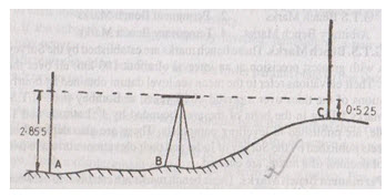
Fig. 24.1. Simple Leveling. (Source: Venkatramaiah, 1996)
Following steps should be used
The telescope of the instrument should be levelled using standard procedure.
The telescope is focused on the levelling staff held vertically on A.
Readings of the central horizontal hair of the diaphragm where it appears to intersect the staff is taken ensuring that the bubble of the level is central.
The staff is shifted to C.
The telescope is directed towards C and again focussed.
Initial levelling should be such that even after rotating the telescope, the telescope remains horizontal.
Reading of the central horizontal line is then taken.
Illustration I
Let the respective readings on staff A and staff C be 2.855 and 0.525m respectively. The difference of level between A and C: 2.855 – 0.525 = 2.330 m
If Reduced Level (R.L.) of A = 500.000 m, R.L of B may be calculated as:
R.L of point A = 500.000m
R.L. of the line of sight = 500.000 + 2.855 = 502.855 m
R.L. of the point C = 502.855 – 0.525 = 502.330 m
Illustration II
If one of the points is on the floor and the other is on the ceilings such as in tunnels or buildings, the staff at the elevated point, may be held vertically inverted (Fig.24.2).
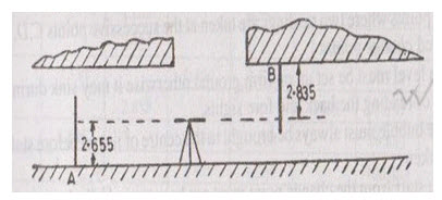
Fig. 24.2. Simple Leveling with Inverted Staff. (Source: Venkatramaiah, 1996)
If the elevation of A = 200.000 m
Back sight reading on A = 2.655 m
Fore sight reading on B = 2.835 m
R.L. of the line of sight = 200.000 + 2.655 = 202.655 m
So, R.L. of the point B = 202.655 + 2.835 = 205.490 m
24.2.2 Differential Leveling
The method of levelling for determining the difference in elevation between two points either too far apart or obstructed by an intervening ground, is known as differential levelling. In this method, the level is set up at a number of points and the difference in elevation of successive points, is determined as in the case of a levelling. Let us suppose that A and B are two points which are far apart and the difference in their elevation, is to be determined by differential levelling. (Fig. 24.3)
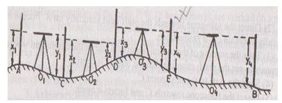
Fig. 24.3. Differential Leveling. (Source: Venkatramaiah, 1996)
Procedure: Following steps are involved.
The level is set up at O1 ensuring that the line of sight of intersects the staff held at A. It is levelled correctly.
With the bubble at central position, take the back sight staff reading on the staff held vertically at A.
Select a point C equidistant from the instrument position O1 and take the fore sight staff reading on the staff reading on the staff held vertically at C.
Shift the instrument to O2, set up and level it correctly.
With the bubble central, take back sight staff reading on the staff held vertically at C again.
Select a point D equidistant from the instrument position O2 and take the fore sight staff reading on the staff held vertically at D.
Repeat the process until the fore staff reading is taken on the staff held on the point B.
Notes: The following points may be noted.
The point where two readings are taken at the successive points C, D, E etc. are called change points.
The level must be set up on firm ground otherwise it may sink during the interval of reading the back and fore sights.
The bubble must always be brought to the centre of its run by leveling the instrument before the staff reading is taken.
The staff from the change point must not be removed till a back sight is taken from the next instrument station by turning round the staff to face the telescope.
Illustration I
Let x1, x2, x3, x4........., xn be back sights and y1, y2, y3, y4....... , yn, be the fore sights taken on the staff held vertically at A,C,D,....etc.
Difference of level between A and C = x1– y1
Difference of level between C and D = x2 – y2
Difference of level between N and E = x3–y3 and so on.
The difference of level of point A and B is equal to the difference of algebraic sum of back sights and algebraic sum of fore sights, i.e. ∑ B.S – ∑F.S. If the difference in level is positive, the closing point B is higher than the starting point A, whereas; if it is negative, the point B is lower than the point A.
Therefore, R.L. of the point B = R.L. of point A ± (∑ B.S – ∑F.S)
24.3 Design of Land Grades
Before grading activities begin, a construction site operator must make decisions regarding the steepness of cut-and-fill slopes and how the slopes will be protected from runoff, stabilized and maintained. Preparation of a grading plan that establishes which areas of the site will be graded, how drainage patterns will be directed and how runoff velocities will affect receiving waters is essential. Also in the grading plan, information about when earthwork will start and stop should be included along with the establishment of the degree and length of finished slopes and where and how excess material will be disposed off (or from where borrow materials will be obtained if needed). Minimization of exposed soils at any given time during construction and incorporation of any berms, diversions, and other storm water practices that require excavation and filling in the plan should be borne in mind. Land grading is therefore a key consideration for construction sequencing.
Care should be taken if blasting agents or explosives are used. These products may contain perchlorates, which are water soluble chemicals. If explosives containing perchlorate are used, then good housekeeping practices should be employed to ensure that any debris is properly disposed. Maintaining undisturbed temporary or permanent buffer zones in the grading operation provides a low-cost sediment control measure that will help reduce runoff and offsite sedimentation.
24.4 Estimation of Earthwork in Leveling and Grading
Earthwork operations are one of the most important construction aspects in road and airfield construction. Earthwork requires the greatest amount of engineering effort from the standpoint of personnel and equipment. Therefore, the planning, scheduling and supervision of earthwork operations are important in obtaining an efficiently operated construction project. Earthwork computations involve the calculation of earthwork volumes, the determination of final grades, the balancing of cuts and fills, and the planning of the most economical haul of material. The exactness with which earthwork computations are made depends upon the extent and accuracy of field measurements, which in turn are controlled by the time available and the type of construction involved. To plan a schedule, the quantity of earthwork and the soil and haul conditions must be known so that the most efficient type and quantity of earthmoving equipment can be chosen and the appropriate time may be allotted. When time is critical, the earthwork quantities are estimated either very roughly or not at all. When time is not critical, higher construction standards are possible and earthwork quantities are estimated and controlled by more precise methods.
The volume of a rectangular object may be determined by multiplying the area of one end by the length of the object. This relationship can be applied for the determination of earthwork by considering road cross sections at the stations along the road as the end areas and the horizontal distance between cross sections as the lengths. The end areas of the cross sections must be computed before volumes can be calculated.
24.5 Methods of End-Area Determination
When the centre line of the construction has been located, measurements are taken in the field from which the required quantities of cut or fill can be computed. A cross sectional view of the land is plotted from these measurements. The cross sections are taken on vertical planes at right angles to the centre line. Where the ground surface is regular, cross sections are taken at every full station (100 feet), where the ground is irregular; they must be taken at intermediate points as determined by the surveyor. A typical cross section is shown in Fig. 24.4.
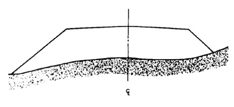
Fig. 24.4. Typical Fill Cross Section. (Source: Venkatramaiah, 1996)
The following steps may be followed for determination of volume of earthwork.
Plot ground elevations from the surveyor’s notes.
Make a sectional template of the sub-grade that shows the finished sub-grade and slopes plotted to the same scale as the cross sections.
Superimpose the template on the cross section and adjust it to the correct centre line elevation.
Trace the template and extend the side slopes to intersect the original ground.
If the section involves both cut and fill, draw only the appropriate lines of each template.
When the sections are completed, begin the end-area measurements, and then determine the volume.
Of the several satisfactory methods of measuring the end areas, only the trapezoidal and planimeter methods are discussed here. The method chosen will depend upon the time available, the accuracy desired, the aids at hand, and the engineer’s preference.
24.5.1 Trapezoidal Method
The trapezoidal method is widely used to determine end areas. The computations are tedious, but the results are accurate. In using the trapezoidal method, the area of any cross section is obtained by dividing the cross section into triangles and trapezoids, computing the area of each part separately and taking the total area of the verticals to the ground line (Fig. 24.5) in order to divide the cross section into two triangles and two trapezoids. Assumption is made that the ground is perfectly straight between these selected points on the ground line. While this is not usually correct, the assumption is within the accuracy normally required.
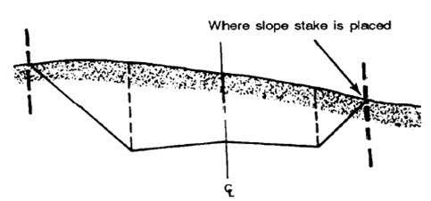
Fig. 24.5. Cross Section in Cut with Verticals Drawn at Critical Points.
(Source: Venkatramaiah, 1996)
Before the area of the cross section can be computed, the basic formulae for the computation of the areas of triangles and trapezoids must be understood.
Computation of Areas: The first step in computing areas by the trapezoidal method is to break the cross-sectional area into triangles and trapezoids by drawing verticals, as shown in Fig.24.5. Then determine the area of these small figures by the appropriate formula. To determine the appropriate dimensions, the notes taken by the surveyors must be known. The cross-section notes taken in the field are in fractional form. The figure below the line indicates the horizontal distance from the centre line to that point on the ground. The figure above the line indicates the ground elevation of that point. Points on the grade line of the proposed road are written in a similar manner and are obtained by computations from the final grade line to be established as shown in Fig.24.8. Thus, the note 32.0/21 indicates a point that is at elevation 32.0 and 21 feet from the centreline of the road. If the cross section is divided into triangles and trapezoid by erecting verticals, obtain notes for the centre line, shoulders, and end of slopes to determine the area.
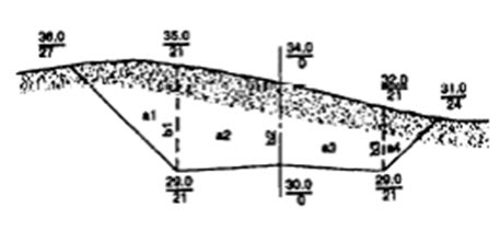
Fig. 24.6. Cross Section Cut Showing Distances and Elevations
(Source: Venkatramaiah, 1996)
To determine areas of the triangles and trapezoids formed, consider the bases of these figures to be vertical and the altitudes to be horizontal. All vertical bases are found by subtracting elevations, and all horizontal altitudes are found by subtracting horizontal distances from the closest vertical in the direction of the centreline.
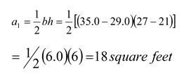
Examples 24.1: Referring to figure 24.6, the area is found out as follows:
Substituting the values in the formula, the area of a triangle is obtained.
substituting in the formula for the trapezoid:
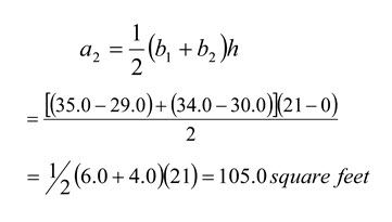
Similarly, all other areas in the figure can be found out with the same procedure.
24.5.2 Planimeter Method
A polar planimeter is an instrument used to measure the area of a plotted figure by tracing its perimeter. The planimeter, shown in Fig. 24.7 touches the paper at three points: the anchor point, P; the tracing point, T; and the roller, R. The adjustable arm, A, is graduated to permit adjustment to the scale of the plot. This adjustment provides a direct ratio between the area traced by the tracing point and the revolutions of the roller. As the tracing point is moved over the paper, the drum, D and the disk, F revolve. The disk records the revolutions of the roller in units of tenths; the drum, in hundredths; and the vernier, V in thousandths.
The accuracy of the planimeter as a measuring device should be checked to avoid errors due to temperature changes and other non- compensating factors. A simple method of testing its consistency is to trace an area of 1 square inch with the arm set for a 1:1 ratio. The disk, drum, and vernier combined should read 1.000 for this area. Before measuring a specific area, the scale of the plot should be determined and the adjustable arm of the planimeter should be set according to the chart in the planimeter case. The setting should be checked carefully by tracing a known area, such as five large squares on the cross section paper and verifying the reading on the disk, drum and vernier. If the reading is inconsistent with the known area, the arm settings should be readjusted until a satisfactory reading is obtained. To measure an area, the anchor point of the adjusted planimeter should be set at a convenient position outside the plotted area. The tracing point is placed on a selected point on the perimeter of the cross section. An initial reading is taken from the disk, drum, and vernier. Tracing is continued on the perimeter clockwise, keeping the tracing point carefully on the lines being followed. When the tracing point closes on the initial point, a reading is taken again from the disk, drum, and vernier. The difference between the initial reading and the final reading gives a value proportional to the area being measured.
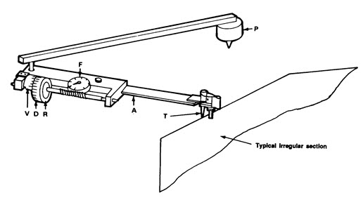
Fig. 24.7. Polar Planimeter in Use. (Source: Venkatramaiah, 1996)
Two independent measurements should be made to ensure accurate results. The first is performed as discussed above. The second measurement is made with the anchor point again placed outside the area being measured but on the opposite side of the area from its position in the first measurement. This procedure gives two compensating readings the mean of which is more accurate than either. To measure plotted areas larger than the capacity of the planimeter, the area is divided into sections and each section is measured separately as outlined above.
24.6 Construction and Maintenance
Construction sequencing is a specified work schedule that coordinates the timing of land-disturbing activities and the installation of erosion and sediment control measures. The goal of a construction sequence schedule is to reduce on-site erosion and off-site sedimentation by performing land-disturbing activities and installing erosion and sediment control practices in accordance with a planned schedule.
Construction site phasing involves disturbing only part of a site at a time to prevent erosion from dormant parts. Grading activities and construction are completed and soils are effectively stabilized on one part of the site before grading and construction commence at another part. A key consideration of grading activities should be the coordination of cuts and fills to minimize the movement and storage of soils on, off and around the site. This differs from the more traditional practice of construction site sequencing, in which site-disturbing activities are performed initially for all or a large section of the site, leaving portions of the disturbed site vulnerable to erosion. To be effective, construction site phasing needs to be incorporated into the overall site plan early. Elements to be considered when phasing construction activities include the followings:
Managing runoff separately in each phase,
Determining whether water and sewer connections and extensions can be accommodated,
Determining the fate of already completed downhill phases and
Providing separate construction and residential accesses to prevent conflicts between residents living in the completed stages of the site and in the area where construction equipment will work later.
Maintance Considerations: All the graded areas and supporting erosion and sediment control practices should be checked periodically, especially after heavy rain falls. All the sediments from diversions or other storm water conveyances should be promptly removed and if washouts or breaks occur, they should be repaired immediately. To prevent small-scale eroded areas from developing into gullies, they should be maintained regularly.
Keywords: Simple leveling, Differential Leveling, Methods of End-area Determination
Suggested Readings
Agor .R, 1979; A Text Book of Surveying and Levelling; Survey of India; Delhi
Venkatramaiah, C. (1996). Textbook of Surveying. Universities Press.
Last modified: Monday, 23 December 2013, 9:36 AM