Site pages
Current course
Participants
General
Module 1. Perspective on Soil and Water Conservation
Module 2. Pre-requisites for Soil and Water Conse...
Module 3. Design of Permanent Gully Control Struct...
Module 4. Water Storage Structures
Module 5. Trenching and Diversion Structures
Module 6. Cost Estimation
Lesson 29. Trenching
29.1 Trenching
Trenching is one of the major engineering measures for erosion control in non-arable lands and is mainly aimed to slope stabilization and drainage line treatment. The area with steep slope e.g. hilly region, are prone to soil erosion due to lack of vegetative cover and accelerated transportation of soil. The hilly area exhibits the characteristics of “high rainfall, quick drainage” that provides little retention time to the runoff to infiltrate into the soil profile. The overland flow velocity is often surpassing the safe limit to cause soil erosion from surface. The trenches constructed in these regions of address the problem of soil conservation to act as flow barrier (restricting the flow velocity within the safe limit from soil erosion point of view) and facilitating in-situ water conservation for establishment of vegetation.
29.2 Types of Trenching
The trenches are constructed in different geometrical configurations namely contour trenching, continuous trenching, staggered trenching and in line trenching. The selection of trenches depends on the site characteristics and rainfall intensity. The schematic diagram of different types of trenches are shown below.
29.2.1 Continuous Trenches
These are series of broad channel or embankments constructed at suitable spacing along the graded contours of gentle slopes. They are suitable for the areas having high annual rainfall. This type of trenches are long trenches (as long as 50 m) and have fixed interval (15 -30 meter). In this type of trenches, horizontal intervals are fixed but vertical intervals are varied. These types of trench are easy to construct but there is a problem of inconsistent deposition of soil in the trenches due to varied vertical interval and hence it is difficult to maintain. The cross-sectional area of the trench is usually kept as 0.25 m2 and depth should not be higher than 0.5 m. The cross section of trenches are kept as square. The life of trench is considered as 5 years. Desiltation is required in every alternate year under normal rainfall condition and every year under excess rainfall conditions.
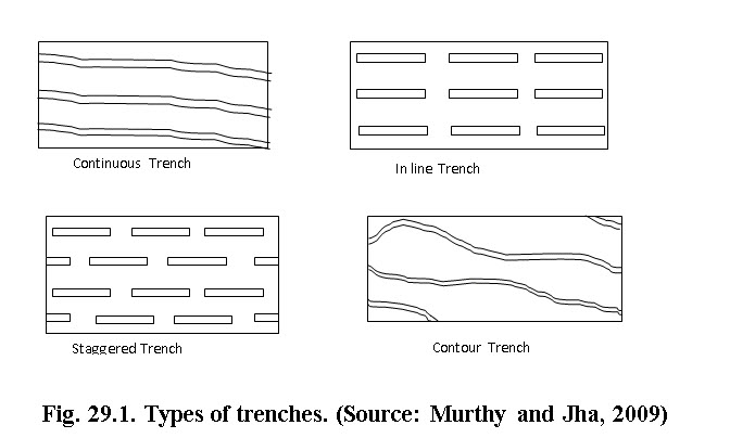
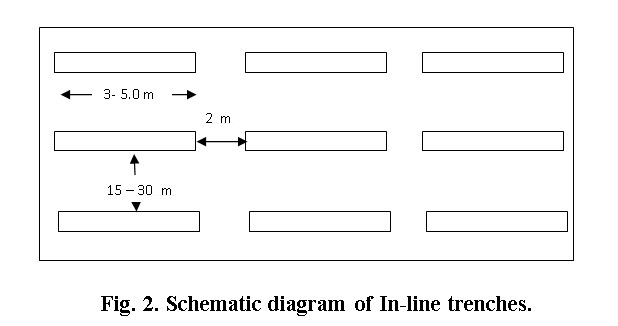
29.2.2 In-line Trench
This type of trench addresses the problem of inconsistent deposition of soil. These trenches are maximum 5 meter long and cross section is similar to continuous trenches. The gap between two in-line trenches should not be more than 2 meters as shown below. This type of trenches has the limitation that it fails to collect runoff flowing between the gaps of two trenches.
 29.2.3 Staggered Trenches
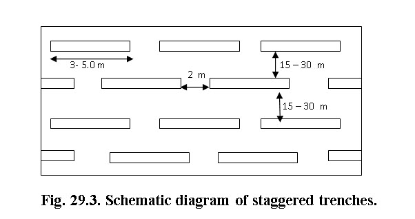
The staggered trenching involves the excavation of trenches of shorter length in a row along the contour with interspace between them. These trenches are arranged in straight line (staggered form). Suitable vertical intervals between the rows are restricted to impound the runoff without overflow. In the alternate row, the trenches are located directly below one another. The trenches in successive rows are thus staggered, with the trenches in the upper row and the interspace in the lower row being directly below each other. The length of the trench and the interspace between the trenches in the same row should be suitably designed such that no long unprotected or uninterrupted slope to cause unexpected runoff or erosion. As the trenches are not continuous, no vertical disposal drain is excavated. The cross sectional area of these trenches should be designed to collect the runoff expected from intense storms at recurrence intervals of 5-10 years.
29.2.3.1 Key Features of Staggered Trenches are:
These trenches are short (3-5 m long) and arranged in row along the contour with inter-space between them.
The vertical interval between two successive trenches is decided on the basis of expected runoff from the area, above without overflow.
In staggered sequenced, the alternate rows of trench are located directly below one another.
The length of row and slope between them fixed based on the concept that, there should not be greater length of unprotected or uninterrupted slope to cause unexpected runoff and erosion.
The cross sectional area of these trenches is designed to collect the runoff from an intense storm during 5 to 10 year’s return period.
29.2.4 Contour Trenching
The contour trenches are similar to continuous trench except it follows the prevailing contour of the area. In contour trenches, the horizontal interval are varying unlike continuous trenches. However, vertical interval is fixed usually kept at 3-5 meters. This type of trenches are little difficult to construct but has the advantages over the continuous trenches in terms of consistent soil deposition and hence easy maintenance and less risk of failure.
Contour Trenches are a simple, low cost method of checking the velocity of runoff in ridge area of any watershed. A contour trenching is excavated trench along a uniform level across the slope of land in the top portion of catchment. Trench along contour line increases retention of runoff for a longer period within the trench and significant reduction in soil erosion. Contour trenching should be carried out perpendicular to the slope. Contour trenches also can be laid as staggered. Contour trenches are widely adopted in soil conservation works.
29.3 Site Specification for Trenching
Following points must be considered while selecting site for trenching.
If the slope of the ridge area is 25% or more, the best form of treatment is the planting of grasses, shrubs and trees. This is because for contour trenches to be effective on such high slopes, they will have to be constructed at very close intervals, which could end up causing more soil erosion due to excessive digging.
On the other hand, if the slopes are less than 10%, then contour trenches are not considered as the best measure. This is because in such a situation, in comparison to contour trenches, contour bunds are a more effective means of checking runoff and soil erosion. In a contour bund, water not only stops in the excavated portion but also against the bund. However, on very high slopes, it is not possible to make contour bunds since there is a great danger of the bunds breaking.
Thus, given the above considerations, contour trenches are the most appropriate where the slope of the ridge area lies between 10-25%. It is an ideal treatment for the non-agricultural land.
If the depth of soil is less than 20cm as well black soil, trenching should be avoided.
29.4 Design of Trenches
The design of trench system involves the trench cross-section, spacing of trenches so as to collect the runoff generated from catchment area. The runoff majorly depends on the hydrologic conditions of the catchment including vegetation, soil and land slope. Following steps are described in designing trenches (Sharda et al 2007).
(a) Determination of Direct Runoff Volume: The trenches are designed such that it should hold the runoff generated from storm of 6-hr rainfall intensity with 5 years recurrence interval. The dimension of trenches are influenced by soil type as well. In cases of coarse textured and fine textured soils, the trenches may be designed to hold 60-70% of the runoff and 50% respectively.
(b) Determining Cross-Sectional Area and Volume: The cross section of the trench can be square, rectangle, trapezoidal or triangle in shape. The choice of shape depends on the soil type and prevailing land slope. Square and rectangular shaped trenches are constructed in relatively flat land with nominal slope whereas in sloppy lands, trapezoidal or triangular trenches are constructed. The cut and fill should be kept equal in trench construction and while computing volume, only cut portion is accounted for.
Trenches are excavated at suitable vertical intervals (depending upon slope of land and soil type). The distance between the two successive trenches depends on the volume and the velocity of runoff they are expected to handle. This in turn depends on:
The quantum of rainfall: The greater the rainfall, the lesser the interval.
The permeability of the soil: The more permeable the soil, the greater shall be the interval
The slope of the land: The greater the slope, the lesser the interval
As the volume and velocity of runoff increase due to any reasons given above, the trenches should become more closely spaced. In practice, one must fix the maximum and minimum horizontal interval between the two successive trenches in a way, which is depicted as follows:
On high slopes, the trenches should be close to each other but should not closer than 10 m.
On low slopes, the trenches should be far from each other but should not more than 30 m.
(c) Determination of Spacing: Spacing, in trenching point of view, are expressed as horizontal and vertical interval (HI and VI). The definition sketch describing various terminology used in trenching is presented below.
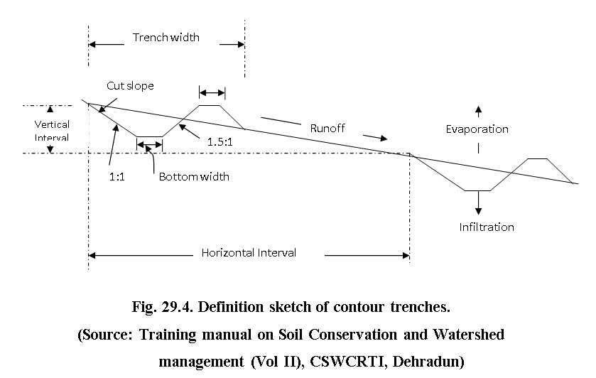
Theoretically, the relationship between horizontal spacing of trenches, runoff depth and trench dimension are described as following:
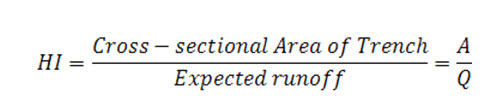
Assuming the trench of rectangular cross section,
In practice, the vertical interval between two successive trenching rows can be measured by:
i) For the vertical interval between two rows.
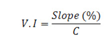
Where,
V.I. = Vertical interval (VI), which is defined as the difference in elevation between the two similar points on two consecutive bunds.
C = 12 for the medium rainfall.
ii) 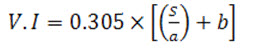
Where VI = Vertical Interval in meter, S = Slope in percent, a and b = constants specific to particular region. For soil with good infiltration rates values of ‘a’ and ‘b’ are respectively taken as 3 and 2 whereas for soils of low infiltration rates the corresponding value are 4 and 2, respectively.
-
Size And Depth of Trench: Size of trench depends on the depth of soil and also on some other factors of watershed. Based on the above parameters different sizes of trenches have been planned. The sizes of trenches are as follows:
|
Sr. No |
Width (m) |
Depth (m) |
|
1 |
0.50 |
0.50 |
|
2 |
0.45 |
0.45 |
|
3 |
0.60 |
0.45 |
|
4 |
0.60 |
0.30 |
|
5 |
0.30 |
0.30 |
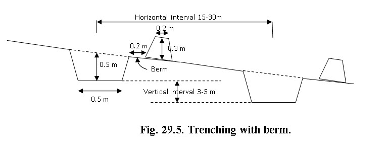
In general, the most popular size has been used in the many watersheds is as follows (Fig. 5):
Depth: 50 cm
Width: 50 cm
Berm: The mud excavated is piled up 20 cm away, downstream of the trench.
This gap between the trench and mud is called the berm. This distance is essential so that this mud does not fill up the trench again.
Plantation: If grass has to be planted along the trenches, then the excavated mud should be piled up in a 10cm. high rectangular layer. If trees have to be planted, they should be planted either in the space after the trench or on either side of the trench.
The general cross section of the trench is given below.
29.5. Planning Contour Trenches
The planning and designing of contour trenches involves 2 factors,
- Amount of runoff water to be stored
- Sufficient length required to store design runoff
Amount of runoff to be stored
It is estimated as the portion of rainfall that results into the runoff and given by the following equation.
![]()
Where,
Q is runoff (m3), C is runoff coefficient, R rainfall (m) and A is the area (m2) of the ridge from which the runoff is received
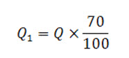
Thus for collecting 70% of runoff in the field
Length required to store design runoff
Cross sectional area of contour trenches is always 0.5 m x 0.5 m = 0.25 m2. The trenches are filled more than once during the rainy period. However, this will depend upon soil permeability and rainfall intensity as well. Usually trenches are designed for at least three filling.
Therefore to store 70% of runoff in an area of one hectare, we divided Q1 by cross-section area (At) of the contour trench multiplied by the number of refills (f).

Laying of trenches
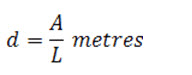
This involves finding out the distance between successive rows of contour trenches and the number of such rows, we have values of area (A) and length of contour trenches (L).
The distance between two successive rows of contour trenches will be,
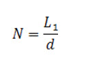
We have to start layout of trenches from the longest section of the ridge area. In order to decide number of rows of contour trenches (N) required, we have to divide the longest section of ridge area (L1) by the distance between successive rows of contour trenches (d).
Example 1: Design a continuous contour trench in area of 25 hectares in Bhubaneswar. The runoff coefficient of this area is 0.4. The daily rainfall is 100 mm and only 75% of the runoff has to be stored in the contour trench. Assume the trench gets 2 refills in a day. The longest section of the ridge area is 2500 m. Make a plan for continuous contour trenching .
Solution:
A= 25 ha = 250000 sq.m
R = 100 mm = 0.1 m
Therefore, Q = 0.4 x 0.1 x 250000 = 10000 cum
Only 75% of run of we want to catch,
Q1= 10000 x 75/100 = 7500 cum
Length of contour trench required,
We knew that usually contour trenches are 0.5 m x 0.5 m, so the cross sectional area is 0.25 sq.m and its given that refills 2 per day.
L = 7500/0.25 x 2 = 15000 m
Distance between successive rows of contour trenches (d),
d = A/L = 250000/15000 = 16.67 m
Number of rows of contour trenches (N),
N= Lt/d = 2500/ 16.67 = 150
Practice Adapted in Indian State Tamilnadu:
Contour and staggered trenches are adapted in high rainfall hilly areas of lands with slopes steeper than 33% or any slope with badly eroded soil. Instead of trenching, graded trenching (modified American) have been suggested. The trenches are limited in length to about 450 m starting from the end farthest from the outlet, trenches run level for 90 -120 m, than on a gradient increasing from 1 in 500 to 1 in 300 at the outlet. The bund or equalizers in the trenches are left closer at about 3 to 4.5 m apart. The trenches are located as below according to slope:
|
Slope Type |
Slope % |
V.I. (m) |
|
Gentle slope |
5- 10 |
13.5 – 19.5 |
|
Medium slope |
10 – 25 |
6 – 13.5 |
|
Steep slope |
More than 25 |
1.25 |
Keywords: Trenching, in-situ water conservation
References
Das, G. “Hydrology and Soil Conservation Engineering.” Prentice-Hall India .
Suresh, R. “Soil and Water Conservation Engineering.” Standard Publishers Distribution.
Central Ground Water Board (2007). “Manual on Artificial Recharge of Groundwater.”Ministry of Water Resources, Govt. of India.
Suggested Reading:
Gurmel singh, C. Venkataramanan, G Sastry and B P Joshi. (1990). Manual of soil and water conservation practices.
Suresh, R. “Soil and Water Conservation Engineering.” Standard Publishers Distribution.
Last modified: Thursday, 13 March 2014, 10:59 AM