Site pages
Current course
Participants
General
Module 1. Perspective on Soil and Water Conservation
Module 2. Pre-requisites for Soil and Water Conse...
Module 3. Design of Permanent Gully Control Struct...
Module 4. Water Storage Structures
Module 5. Trenching and Diversion Structures
Module 6. Cost Estimation
Lesson 30. Diversions and Ditches
30.1 Diversion
Diversions are the water conveyance structures that are constructed to intercept the surface runoff and transport to the main drain. The major purpose of the diversions and ditches is to convey runoff to a suitable disposal point at non-erosive velocity. The complete system to dispose excess water from surface includes: Diversion channels, ditches and grassed waterways. Diversions are constructed at the point where the soil is susceptible to be eroded due to the surface runoff attaining erosive velocity. The diversions are constructed across the prevailing slope and divert it across the slope of grassed waterways. Both diversion and ditches are in form of channel or trench with gentle slope. However, in case of ditch, the channels are deeper as compare to diversion. Grassed waterways designed to transport excess runoff down the slope to the natural drainage system.
Diversion – The design of field channel, diversion channels and grassed water ways includes the determination of cross-section for design discharge and velocity of flow. The cross section and channel slope should be sufficient to handle the design flow and maintain the flow velocity within permissible limit.
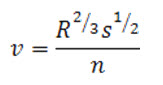
The average velocity of flow is estimated using Manning’s equation.
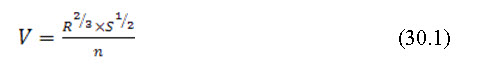
Where, is average velocity of flow (m/s), is hydraulic radius (ratio of cross sectional area of flow, A and the wetted perimeter, P). Wetted perimeter, P defined as the length of cross-section, which is in contact with the flowing water and so it depends on depth of flow, D. S is hydraulic slope (m/m) and n is the Manning‘s roughness coefficient.
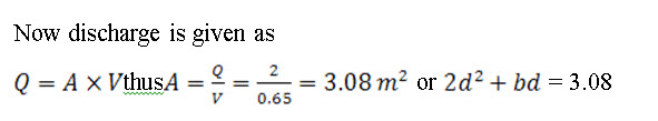
Discharge capacity of the of the channel is estimated using the continuity equation
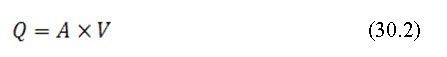
Where, Q is discharge (m3/s), A is cross sectional area (m2) and V is average velocity (m/s).
30.1.1 Diversion – Criteria for Selection
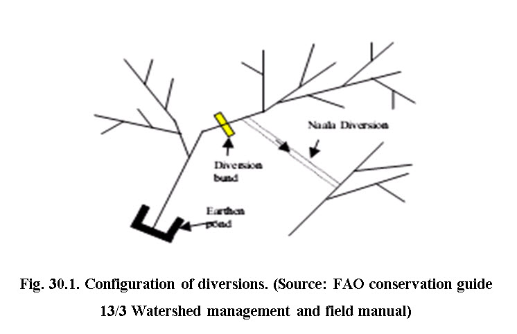
The slope is the main criteria for selection of diversion. The dimensions of diversion depend on the quantity of runoff to be intercepted and transported to the main drain. Fig.30.1 presents the concept of the diversion. The configuration of diversions is like dendrogram. The diversion are provided to prevent the advance of the gully erosion. The considerations for selection of location are:
where above slope runoff endangers the low-lands;
where gully is progressing and its head cutting has reached to advanced stage;
Part of the farm where runoff is concentrated and
Where there is a need to collect additional water particularly to divert runoff to the farm pond or natural drainage system.
30.1.2 Most Economical Channel Section
The most economical channel section provides maximum flow rate at minimum excavation or amount of construction material and labor. Theoretically, highest possible hydraulic radius for given cross-sectional area would provide most economical cross-section. For these conditions, semicircular cross-section is most economical since it has minimum wetted perimeter. Generally, semi-circular cross section is difficult to construct except smaller lined channel. Trapezoidal section is most adopted because it is easy to construct. The discharge in trapezoidal cross-section is maximum when the bottom width equals to (), in which, d is the depth of flow and is the angle of inclination of the side to the bed. For rectangular section, remains zero and hence in this case the bottom width would be equal to 2d.
30.1.3 Design Specification for Diversion
The design specifications involve the determination of runoff volume to be conveyed and suitable dimension of the diversion channel. Following points should be considered while designing the diversions.
a) The length should not exceed 350 m.
b) Quantity of runoff should be estimated for 10 years return period for agricultural land.
c) The maximum velocity in the channel should be limited as per Table 30.1
Table 30.1. Safe limit of flow velocity under different soil covered channel
|
Soil type |
Safe limit (m/s) |
|
Sandy soil |
0.4 |
|
sandy loam and silt loam |
0.6 |
|
Clay loam |
0.65 |
|
Clay |
0.70 |
|
Gravelly soil |
1.0 |
(Source: FAO Conservation Guide 13/3)
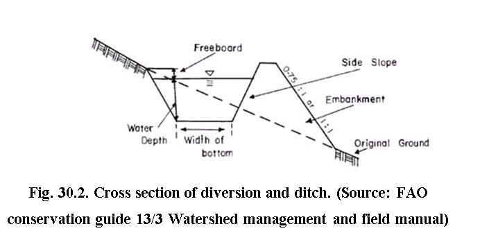
A free board of 10-30 cm may be added to the depth of flow as a safeguard. Usually, the carrying capacity of the channel is higher than designed runoff to provide extra protection. The cross section is determined by the amount of runoff, designed velocity of flow and shape and side slope of the diversion and ditches. Fig. 30.2 shows typical cross-section of diversion ditch. The design of ditch can be adjusted by increasing the cross-section and gradient to accommodate larger amounts of run-off. However, the velocity of the flow should not exceed the safe limits explained earlier. Another design modification is to make the ditch's side slope and gradients less steep on sites where the soils are prone to erosion.
30.1.4 Design Procedure
The design of flow channel includes determination of flow rate to be carried out by the channel; selection of suitable channel bed slope based on topography and soil type; Selection of suitable channel shape and side slope; finding cross sectional area and wetted perimeter; estimating velocity of flow using manning’s formula; Validating flow velocity to be within permissible limit and finally providing free board (about 15-20% of the depth of flow) to determine total depth of channel.
Example 30.1: Design a trapezoidal diversion channel to carry design discharge of 2 cumec to the reservoir through earthen channel. The prevailing slope is 0.001 m/m and soil type is clay loam. Take Manning’s roughness coefficient as 0.03.
Solution:
The permissible velocity for this type of soil is 0.65 m/s. Using Manning’s equation, determine hydraulic radius, R
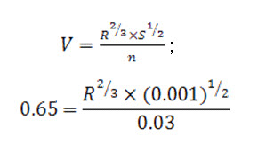
Thus hydraulic radius, R = 0.49 m
The hydraulic radius for trapezoidal section,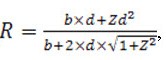 , where b,d and z are bottom width, depth of flow and side slope, respectively. For clay loam soil, the side slope should be 2:1 i.e. Z =2, Thus
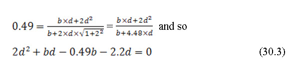
Thus equation 3 modifies to
For most economical cross section, ![]() , since side slope, Z is 2, Ø will be 60o thus
, since side slope, Z is 2, Ø will be 60o thus ![]() would be equal to 0.5. so for most economical cross-section,b=d , substituting this to equation 30.4
would be equal to 0.5. so for most economical cross-section,b=d , substituting this to equation 30.4
Adding 15% free board, total depth of channel will be 1.32 m say 1.35 m
Hence top width, T = b+2Zd = 1.15+2x2x1.35 = 6.55 m.
Example 30.2: Design a grassed waterway which is to be constructed as an outlet for flow from a graded bud system. The expected runoff is 2.9cumec. The type of grass to be used is dub and needs to be maintained in excellent way. The slope of the channel is to be kept at 3.5%.
Solution:
The problem (waterway designed) can be solved by trial and error method,
Assume the top width (t) of the water way = 4.75 m,Depth of flow (d) = 0.45 m
For parabolic channel, cross section area (a) = 2/3 td = 1.425 m2
Wetted perimeter (p) of the waterway = t + 8d2/3t = 4.86 m
Hydraulic radius (R) of the waterway = a/p = 0.293
Mean velocity by using the Manning’s formula
Where s = channel slope = 3.5/100
n = 0.04 for natural channels
Therefore, v = 2.07 m/s
Flow capacity Q of the water way = a x v = 2.95 cumec
The discharge capacity is slightly more than 2.95cumec and thus it’s acceptable. The velocity is also within the permissible limits, Hence the design is acceptable where t = 4.75 and d = 0.45 m.
30.2 Ditches
Ditches are primarily components of surface drainage system that used to remove excess water in soil having slow infiltration, low permeability and no quick percolation. The ditch system is designed to remove surplus water within 12-24 h. Depending upon the alignment, different categories of ditch systems are described below (Sharda et al. 2007).
(i) Random field ditch system
(ii) Bedding system
(iii) Parallel field ditch system
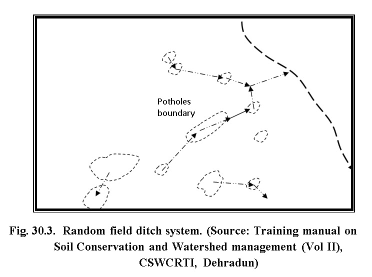
30.2.1 Random Field Ditch System
Random field ditch system, as shown in Fig. 30.3, is best suited in the area which have randomly scattered depression or potholes and depth of cut is limited to 1 m. In this system, the depth of ditch is low to allow movement of farm equipment across. The cross section can be rectangular, triangular or parabolic and can be constructed using tractor mounted field equipments. While aligning the ditches, it should follow such a route that provides minimum cut and interference with other agricultural operations. For effective removal of excess water, the ditches may be supplemented with land grading. The outlet of this system is natural stream.
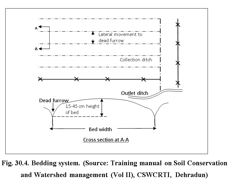
30.2.2 Bedding System
In this system, the ditches comprises of dead furrows that run parallel to the prevailing slope. The area between two adjacent dead furrow is known as bed (Fig. 30.4). These beds are aligned such that the farming operations are parallel to the dead furrows. The design and layout involves proper spacing of dead furrow to remove the excess water within 24 hours.
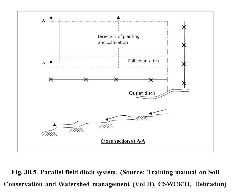
30.2.3 Parallel Field Ditch System
In this system, the channels are spaced widely with higher flow capacity and cultivation done across the field slope unlike bedding system. This system is most suited for flat and poorly drained soil conditions. The ditches are not necessarily spaced equally and size of ditches can be varied as per the land grading, and size of drainage area. In this system ploughing are done parallel to the system (30.5).
30.3 Design Consideration of Ditch System
The ditch system includes determination of cross sectional area and discharge is same as design of diversion considering the same side slope and permissible velocity criteria. However, the design of ditch system further influenced by factors such as maximum 1 day rainfall occurance with a frequency of 5 years; infiltration rate of soil; evaporation rate; crop grown and stages; land slope and gradient to the drainage channel. The gradient should normally follow the natural slope of the land.
Example 30.3: The drainage coefficient of an area of 40 ha is 0.4 m. Estimate the capacity of the ditch system draining the area.
Solution:
The drainage coefficient = 0.4
Total quantity of water to be drained within 24 hours = 0.4(40X100X100)
= 160000 m3
Thus flow rate = 160000/(24*60*60) = 1.85 cumec.
References:
-
FAO, (1988). Watershed management field manual - Slope treatment measures and practices”. FAO technical paper 13/3, FAO, Roam.
-
Das, G. (2000). Hydrology and Soil Conservation Engineering.” Prentice-Hall India.
-
Suresh, R. (1993). “Soil and Water Conservation Engineering.” Standard Publishers Distribution, New Delhi
-
Sharda, V.N., Juyal, G.P., Prakash Chandra and Joshi, B.P. (2007). Training Manual – Soil Conservation and Watershed Management (Vol II Soil and Water Conservation Engineering). CSWCRTI, 218, Kaulagarh Road, Dehradun.
Suggested Readings
-
Suresh, R. (1993). “Soil and Water Conservation Engineering.” Standard Publishers Distribution, New Delhi
-
Sharda, V.N., Juyal, G.P., Prakash Chandra and Joshi, B.P. (2007). Training Manual – Soil Conservation and Watershed Management (Vol II Soil and Water Conservation Engineering). CSWCRTI, 218, Kaulagarh Road, Dehradun.
Last modified: Friday, 14 March 2014, 7:24 AM