Site pages
Current course
Participants
General
MODULE 1. PRINCIPLES AND TYPES OF CUTTING MECHANISM
MODULE 2. CONSTRUCTION AND ADJUSTMENT OF SHEAR AND...
MODULE 3. CROP HARVESTING MACHINERY
MODULE 4. FORAGE HARVESTING, CHOPPING AND HANLING ...
MODULE 5. THRESHING MECHANICS, TYPES OF THRESHES, ...
MODULE 6. MAIZE HARVESTING AND SHELLING EQUIPMENT
MODULE 7. ROOT CROP HARVESTING EQUIPMENT
MODULE 8. COTTON PICKING AND SUGARCANE HARVESTING ...
MODULE 9. PRINCIPLES OF FRUIT HARVESTING TOOLS AND...
MODULE 10. HORTICULTURAL TOOLS AND GADGETS
MODULE 11. TESTING OF FARM MACHINES, RELATED TEST ...
MODULE 12. SELECTION AND MANAGEMENT OF FARM MACHIN...
LESSON 3. SHEAR TYPE CUTTING MECHANISMS, ADJUSTMENTS, REGISTRATION AND ALIGNMENT
It has knife that moves against stationary fingers. Horizontal reciprocating type mower has knifes that rotate at high speed in horizontal plane (Fig. 1). Due to reciprocating action of knife, grasses are cut uniformly. The mower/reaper consists of following parts:
Cutter Bar: Cutter bar is designed to cut 25-50 mm above the ground level up to 100 mm or more. It must be able to cut a wide variety of crop materials from grasses to tough stocks without clogging. A number of attempts have been made to replace the reciprocating knife with continuous moving cutting units such as chain or band knives in helical roller cutters but none have performed so well that commercially feasible. It is steel flat made with high-grade steel. All other sub component included in the cutting mechanism is connected directly or indirectly to it.
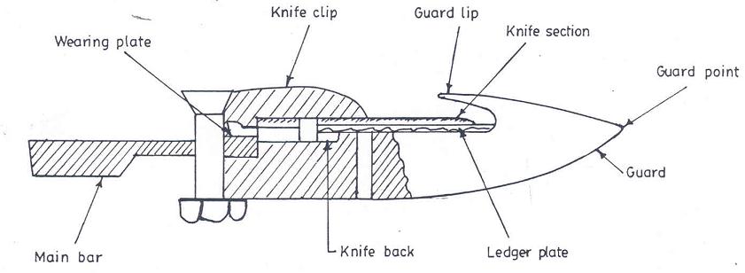
Cutter Bar Assembly: It is heart of the mower. The knife is metal bar on which blades are mounted that are triangular shaped sections. The cutting edges of these sections are mostly smooth edges. The knife sections move back and forth and cut plants in both directions. The section of the knife should always stop at the center of the guard on each stroke. The length of the stroke is 7.5 cm. Guards are provided with ledger plates on which the knife sections move. Knife clips hold the sections down against ledger plates but allow it to move freely. Knife clips are placed together with the wearing plates to absorb the rearward thrust of the crop to the knife. A badly worn wearing plate or a loose knife clip may allow the knife to bend. This is a common cause of the knife head, breaking at the point where it is attached to the bar. There is a grass board on the outer end of the mower, which causes the cut plants to fall towards the cut material. The angle of the board can be changed for different crops. A shoe on each end of the cutter bar is always provided to regulate the height of the cut above the ground. The inner shoe has a larger area of contact with the ground than the outer one. This results in smooth and easy sliding of the cutter bar on the ground.
Guards: These are provided to hold the forage while it is being cut. These also serve to secure the cutting units and provide a place for the ledger plates. The guards are made with malleable casting or pressed steel, pointed at one end for parting and guiding the grass to the knife sections.
Ledger Plate: The ledger plates are fixed over to the guards. They form one half of the cutting unit, the knife section acts as the other half. The edges of ledger plates are serrated to prevent stems of grass from slipping off the points of the shears.
Knife Section: Triangular shaped knife sections are fixed over to the cutter bar. The rear part of knife section is kept square shaped for its easy fixing. These are perfectly smooth and work well in most of the grass and legume crops. Some sections are top serrated which work well in dry grass or straw.
Wearing Plates: Wearing plates supports the knife from rear side. They provide vertical support to the rear of the knife sections and also absorb the forward thrust of the knife.
Knife-clips: These are provided to hold the knife section down close against the holder plates. They are made of malleable iron or steel. Knife clips are generally spaced three or four guards apart.
Inside Shoe: The inner end of the cutter bar during the operation is supported with a shoe like runner. A replaceable sole is placed underneath the shoe, which is adjustable to regulate the height of cut.
Outside Shoe: The outside shoe supports the outer end of cutter bar. It also has an adjustable sole to regulate the height of cut. The pointed front part of the other shoe acts as a divider. It separates the cut grass from standing uncut grass.
Power Transmission Unit: The knife of cutter bar is powered through a long pitman attached to the knife head. The power transmission consists of main axle, gears, crankshaft, crank wheel and pitman. The main axle receives power from one of the transport wheels. A spur gear mounted on the main axle drives the spur pinion on one end of the counter shaft in the gearbox. The bevel gear, which is provided to the other end of the counter shaft, engages with the bevel pinion on the crankshaft. The crank wheel and pitman are fixed on the outer end of crankshaft and the reciprocating motion is transmitted to the pitman, which in turn operates the knife in the cutter bar. The knife is connected to the pitman with a ball and socket joint. Crank speeds on most of the mowers are 850-1000 rpm for conventional pitman drives and 1000-1200 rpm for dynamically balanced systems. The knife makes about 1600 cutting strokes per minute. The tractor-drawn mowers are operated by PTO shaft. Most tractor-drawn mowers have a V-belt in the drive which provides overload protection and check high frequency peak torque and shock loads, sometimes dog clutch or a slip clutch is provided.
Wheels: A pair of wheel made of cast iron with sufficient widths and number of lugs to develop better traction are provided in the mowers. Now, pneumatic wheels are also in use. The transport wheels transmit power to the knife. It is so arranged that when the wheel move forward the ratchet and pawl mechanism comes into play to drive the main axle. When the wheel is turned backward the pawl slips giving a clicking noise.
Frame: The main frame of the mower is made with heavy casting that supports other parts and provides openings for main axle, counter shaft and crank shaft. It provides space for gearbox, clutch and bearing. A triangular shaped welded frame is common in semi-mounted mowers over which power transmission unit is installed.
Pitman: The pitman is the connecting rod between the crank wheel and the knife. Pitman may be made of well-seasoned wood or of steel which supports weight and absorbs vibrations.
Grass Board and Stick: The grass board is provided to clear the cut material from narrow strip next to the standing crop and hence provide a place for the inner shoe for operation on the next turn. A stick is also provided to keep the forage falling correctly. It can be set high for tall grass and low for short material. The grass board is spring loaded and free to move to some extent when it meets an obstruction.
Adjustments: A system of force acts upon the material to cut it in such a manner as to cause it to fail in shear. A common way to apply the cutting force is by means of two opposed shearing elements, one or both may be moving. The motion may be linear with uniform velocity, reciprocating or rotary. Impact cutting principle is applied in rotary cutters and flail shredders. A continuous reciprocating knife type of cutter bar is commonly used to cut a wide variety of crop materials. Cutting in this case utilizes both impact and shear. There are two adjustments, which are very important for proper functioning of a mower. They are registration and alignment.
Registration: A knife is in proper registration when midpoint of the knife section stops in the center of guard on each stroke (Fig. 2). It is very essential for an even job of cutting and unclogging of the cutter bar. If it is not properly registered then it can be adjusted by moving the entire cutter bar in or out with respect to the pitman crankshaft. The results of failing to register are an uneven cutting and an uneven loading of the entire mower. It also results in more draft and clogging of knife. There is provision to change the pitman length, which is provided in some of the mowers.
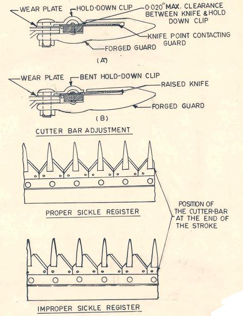
Fig. 2: Adjustment in the cutter bar unit.
Alignment: The outer end of the cutter bar is fitted a little ahead of the inner end so that the outer end may align with the inner end, when the mower is pulled through crops. This is called lead and gives better cutting when the cutter bar is properly aligned i.e. the knife and the pitman run in a straight line. To allow for rear word deflection of the outer end of cutter bar during operation, it is customary to adjust the mower so that when not in operation, the outer end of cutter bar has a lead of about 2-cm per meter of cutter bar. To measure the lead of a mower, stretch a stirring parallel to the vertical plane of the pitman and determine the difference in the horizontal fore-and-aft distances from the string to the knife back at the inner and outer ends. Adjustment, if needed be done by rotating an eccentric bushing on one of the hinged pins. Fig. 3 shows a typical arrangement of a pitman drive and inertia-force relations for the reciprocating knife, pitman and crankpin. Pitman mass is assumed to be divided into two components, W1 being subjected to rotary motion and W2 having reciprocating motion. If Ws is the mass of knife and Wc is the mass of crankpin, uniform angular velocity of the crank can be assumed if R/(L2 - S2)1/2 is less than 0.25. The inertia force of the reciprocating parts can be represented by the equation
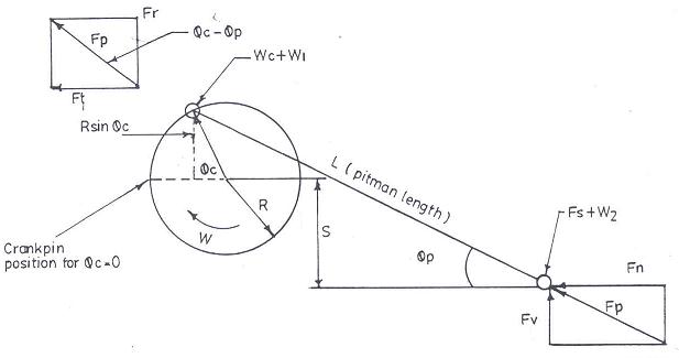
Fig. 3: Forces due to inertia of reciprocating parts in a mower pitman drive.
(Kepner et al. 1987)
K S
Fh = (Ws + W2) R w2 (cos jc + ------ sinjc - K cos 2jc ) ------- (1)
R
Where,
Fh = inertia force of the knife
W2 = portion of pitman mass during reciprocating motion
w = angular velocity of crank, radians/s
L = length of pitman
jc = angle of crank rotation
R = radius of rotation of crank pin
S = height of crank shaft center line above the plane of pivot connection
Between knife and pitman
K = R/(L2 - S2)1/2
Because of angle between pitman and knife, a periodic vertical reaction Fv, alternating upward and downward, is introduced at the knife head. If the knife head guides are loose may cause early fatigue of knife back. Cutting energy and power requirements of a 2.13 m tractor-mounted mower is given in Table 1. Height of cut of crop can be adjusted by varying the adjustable shoes at the inner and outer ends of the cutter bar.
Table 1: Cutting energy and power requirements of a 2.13-m tractor-mounted mower.
|
|
Average Equivalent Knife Load (kN) |
Average PTO Power (kW) |
Average Peak PTO Power (kW) |
|
Inertia & friction load (no cutting) |
1.82 |
1.27 |
4.61 |
|
Mowing at 7.9 km/h |
2.54 |
1.90 |
5.22 |
|
Increase due to cutting |
0.72 |
0.63 |
0.61 |
Source: Kepner et al. 1987
Last modified: Tuesday, 18 March 2014, 5:51 AM