Site pages
Current course
Participants
General
MODULE 1. PRINCIPLES AND TYPES OF CUTTING MECHANISM
MODULE 2. CONSTRUCTION AND ADJUSTMENT OF SHEAR AND...
MODULE 3. CROP HARVESTING MACHINERY
MODULE 4. FORAGE HARVESTING, CHOPPING AND HANLING ...
MODULE 5. THRESHING MECHANICS, TYPES OF THRESHES, ...
MODULE 6. MAIZE HARVESTING AND SHELLING EQUIPMENT
MODULE 7. ROOT CROP HARVESTING EQUIPMENT
MODULE 8. COTTON PICKING AND SUGARCANE HARVESTING ...
MODULE 9. PRINCIPLES OF FRUIT HARVESTING TOOLS AND...
MODULE 10. HORTICULTURAL TOOLS AND GADGETS
MODULE 11. TESTING OF FARM MACHINES, RELATED TEST ...
MODULE 12. SELECTION AND MANAGEMENT OF FARM MACHIN...
LESSON 4. IMPACT TYPE CUTTING MECHANISMS
The impact/ cutting mechanisms are of a rather recent development. They depend upon the effective shear of the material to be cut by a sharp impact of blade(s) travelling at 1300 to 2700 m/min. The more rigid the stalks and therefore resistant to bending, the more easily they gives way through shear failure/ under impact. The impact cutting mechanisms are being used in the rotary mowers (also called flail type) and forge harvesters with great advantage. Greatest efficiency is derived from the use of sharp edged, long rotating blades to have higher peripheral speed and higher inertial momentum of the heavy blades to sustain their speed when cutting dense-growth. To utilize the impact-shear principle effectively, it is essential to employ a mechanical prime mower. The manually-carried Japanese power reaper with a circular blade employs the impact cutting principle. The advantages of impact-cutting mechanism are the minimum initial cost, simplicity of repair and maintenance as well as high efficiency. The impact-type mechanisms are particularly well-suited to rough land and rough pasture. The impact-type cutting mechanisms are, however, not suited to harvesting grain crops due to higher shattering of the grain as well as the spreading of the stalks upon being cut.
The flail type forage harvesting is simple in design and construction. It can be used for cutting any type of forage crops and grasses including lodged crops. Overload encountered by the machine during operation is absorbed by freely hanging flails and thus machine components are protected from field damage. This makes it a unique machine to be used in stony, stumpy and uneven land. Forage crops cut by flail mower do not require any additional chopping by chaff cutter. This is done in the process of harvesting in the field itself by repeated beating action of the flails on the plants. Tractor rear mounted hydraulically controlled PTO operated flail type forage harvesting machine is versatile for numerous field operations such as fodder maize cutting, grass topping and mowing, green manure topping, cutting shrubs on river banks and drainage channels etc.
A flail-type mower comprises of a horizontal rotor with two blades each of about 60 cm. The blade rotates at peripheral speeds of 2000-3000 rpm (Fig. 1). These mowers are extremely sturdy and as such can work under varying field conditions. When used for grasses, it causes excessive field loss as short pieces are hardly recovered in raking or during picking from the windrows. Losses can be reduced using lower peripheral speeds. A flail mower has a full width adjustable gauge roller located behind the rotor to provide accurate control of cutting height and prevent scalping of high spots. Cutting widths are usually 1.8 to 3.0 meters. Pull type flail mowers are generally attached at the back of tractor and kept offset so that the tractor wheel runs on the cut hay rather than on the standing crop. Some of these units are provided with augurs to convey the cut material into trailers. It uses free-swinging chains and knives to sever the plants by beating or cutting action (Fig. 2). The flails or knives travel in the same direction the machine moves. It does not have chopping knives on the blower fan to chop the material into desired length for silage. The beating by flails more or less conditions the hay.
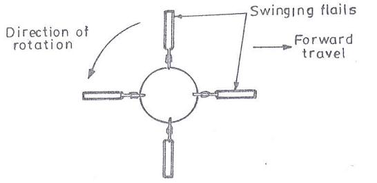
Fig. 1: Flail action during work.
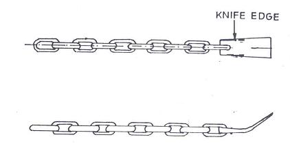
Fig. 2: Details of free swing chains.
Problem 1: Determine horizontal inertia force at each end of stroke and magnitude and direction of vertical reaction at each end of stroke for reciprocating cutter bar knife in a mower. Given:
Crank speed = 1000 rpm; pitman length = 1.06 m; crank pin radius = 38 mm; mass of knife = 4.4 kg; mass of pitman = 3.5 kg; mass of crank pin = 0.35 kg; centre of gravity of pitman = 0.48 m from knife end and height of crank shaft centre line above pivot connection between knife and pitman = 240 mm.
Solution: Refer to Fig. 3 and equation 1 in lesion 3
Weight of pitman (W1 + W2) = 3.5 kg
Since centre of gravity of pitman is 0.48 m from knife end,

Inertia force at each end of stroke can be calculated by putting jc = 00 and jc = 1800
For φc = 00
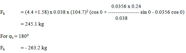
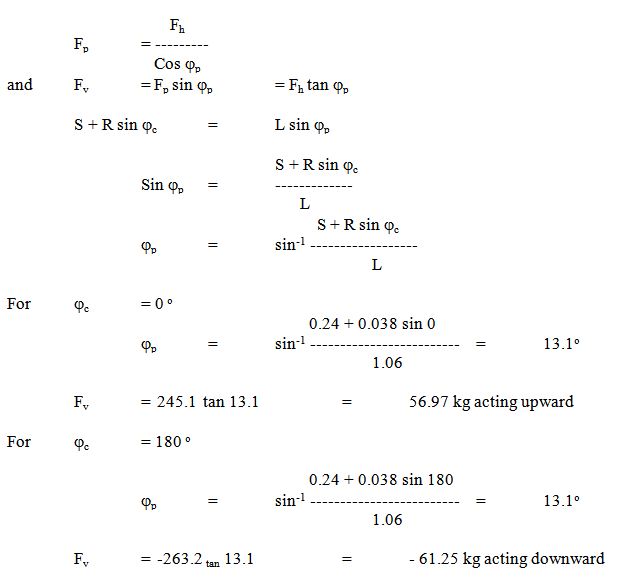
Since, the pitman and cutter bar are not in the same plane, an intermittent vertical force will be introduced at knife head at each end of the stroke.
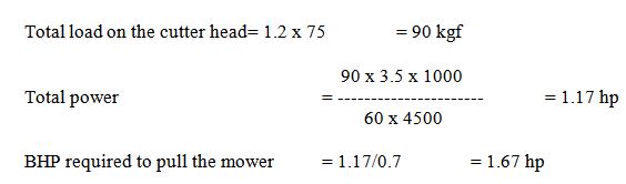
Problem 2: A 1.2 m mower is working at a speed of 3.5 km/h and experiences a load of 75 kgf/m length of cutter head. What will be the horse power requirement if mechanical efficiency of mower is 70%.
Solution:
Problem 3: A trailed type mower has drive wheel of 65-cm diameter. The crank of mower makes 850 rpm when it is hitched to a tractor moving at a constant speed of 3 km/h. If the speed ratio between the crank wheel and land wheel is changed to 30:1, calculate the increase in speed of mower to maintain same speed of crank.
Solution: rpm of crank = 850
rpm of drive wheel = 850/30 = 28.33
Linear speed of mower = p D R = 3.14 x 0.65 x 60 x 28.33/1000
= 3.47 km/h
Increase in speed of mower = 3.47 - 3.0 = 0.47 km/h
Where, D = diameter of drive wheel
R = rpm of drive wheel
Last modified: Wednesday, 11 September 2013, 9:44 AM