Site pages
Current course
Participants
General
MODULE 1. PRINCIPLES AND TYPES OF CUTTING MECHANISM
MODULE 2. CONSTRUCTION AND ADJUSTMENT OF SHEAR AND...
MODULE 3. CROP HARVESTING MACHINERY
MODULE 4. FORAGE HARVESTING, CHOPPING AND HANLING ...
MODULE 5. THRESHING MECHANICS, TYPES OF THRESHES, ...
MODULE 6. MAIZE HARVESTING AND SHELLING EQUIPMENT
MODULE 7. ROOT CROP HARVESTING EQUIPMENT
MODULE 8. COTTON PICKING AND SUGARCANE HARVESTING ...
MODULE 9. PRINCIPLES OF FRUIT HARVESTING TOOLS AND...
MODULE 10. HORTICULTURAL TOOLS AND GADGETS
MODULE 11. TESTING OF FARM MACHINES, RELATED TEST ...
MODULE 12. SELECTION AND MANAGEMENT OF FARM MACHIN...
LESSON 8. FORAGE CHOPPING AND HANDLING EQUIPMENT; RAKES AND BALERS
Field Choppers
The machines are available both as a tractor-drawn and self-propelled type. PTO of tractor drives some tractor-drawn field choppers while an auxiliary engine mounted on the machine drives others. The offset hitch permits the chopper to trail to the right of tractor so that tractor does not run over the crop. The cutter bar consists of a regular mower like cutter bar and a reel to throw the crop back onto an apron which conveys the material to auger, which takes into the chopping unit. In this machine, there are two types of cutter heads: flywheel-type and cylinder-type. In the flywheel-type cutter head, knives for cutting and impeller paddles for throwing and blowing are mounted on the wheel separately. The cylinder-type cutter head has knives designed both to cut and blow but in some cases separate impeller blower is provided. The cylinder-type cutter head has built-in sharpeners, but knives are removed from the flywheel for sharpening. The capacity of a field chopper is affected by area of throat opening, speed and rate of feeding and density of material, which in turn is affected by yield of the crop.
The capacity of field chopper can be calculated by:
C = 60 h D L W H n N ------------ (1)
Where,
C = capacity of field chopper, kg/h
h = field efficiency
D = bulk density, kg/m3
L = length of cut, m
W = width of throat, m
H = height of throat, m
n = number of knives
N = rpm of flywheel
Chaff Cutters
Green fodder crops are essential food requirement for on-farm animals. These fodder crops are harvested from the field daily either by sickles or reapers. Then crop is collected from the field and carried to the farmhouse where it is cut into small pieces. This is done to save storage, to aid in curing and to make it more palatable. The cutting of fodder into small pieces is done either manually using ‘Gandasa’ or by using manually or power operated chaff cutters. Depending on the type of cutting head, chaff cutters may be classified as cylinder cutting head machine and flywheel type cutting head machine. According to power used chaff cutters are classified as hand chaff cutters, animal operated chaff cutters and power chaff cutters or silage cutters.
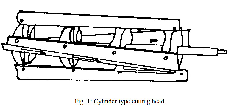
Cylinder type cutting head chaff cutter: It is commonly used on power chaff cutters. This type of cutting heads is sometimes used on field forage harvesters that cut the fodder crop from the field, chop and blow into wagon. The machine consists of four spiral-shaped knives on a revolving cylinder, which looks like the rotary lawnmower (Fig. 1). The knives can be sharpened without being removed from the cylinder. The size of chaff can be adjusted by changing the speed of feed rollers provided adjacent to the shear plate. The chopped material fall into housing from where it is stored at a proper place. This type of machine is not commonly used in India and is more costly as compared to flywheel type machine.
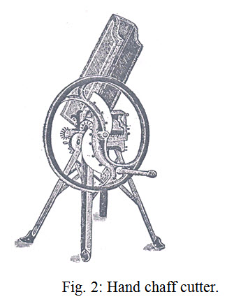
Flywheel type chaff cutter: It consists of a cast iron flywheel and radial mounted knives (Fig. 2). Straight knives are used on power chaff cutters and curved knives on hand chaff cutters. The number of knives varies from two to six depending upon the type of chaff cutters and size of chaff desired. Hand operated chaff cutters are provided with two knives only. Some power chaff cutters of large size have blower used for silo filling. The average working speed of hand chaff cutter is 50 rpm with one knife and 35 rpm with two knives. The power operated chaff cutters are operated at working speed of 600-1000 rpm. For proper cutting of silage, knife should operate close to the shear plate without striking. Clearance between the shear plate and knife can be adjusted by a set of screws provided for the purpose. The knife is fastened on the flywheel by means of two or three counter sunk bolts.
The size of chaff or length of cut can be changed by changing the speed of feed rollers. Hand operated chaff cutters are provided with a two speed worm for adjusting the length of cut where as two or three speed gearbox has been provided on power operated chaff cutters. Reducing or increasing the number of knives on the flywheel can also changes the length of cut of silage. This can be done easily on the hand operated chaff cutters. On power operated chaff cutters, length of cut of silage can be adjusted by increasing the speed of cutter head. The length of cut of silage varies from 20-40 mm and for green fodder 25-50 mm or sometimes more.
The feeding mechanism of a power operated chaff cutter consists of an apron and two feed rollers. Aprons are generally provided with metal or wooden slates to give a positive feed. The length of the table on which the apron moves is about 2 m so as to accommodate tall grasses or fodder crops. Spring-loaded feed rollers are provided to compress and feed the uncut material to the cutting head. Generally, corrugated or toothed rolls are preferred. Hand operated machines are not provided with aprons. A feed-table or merely a feed box is considered to be enough for this machine and the feeding is done by hand. Feed rollers of the hand-operated machine have variable spacing and the worm mounted on the flywheel shaft operates them. The bullock operated chaff cutters is similar to hand operated one but it is provided with a smaller diameter flywheel on which two or three knives are mounted. By means of a set of gears and universal joints, the slow speed of bullocks is utilized to operate the machine at about 250 rpm and thus its capacity becomes 4 to 6 times more than that of the hand operated machine. The capacity of the chaff cutters can be calculated by:
C = 60 x 10-3 D L W H n N ------------------- (2)
Where,
C = capacity of machine, t/h
W = width of throat, m
H = height of throat, m
L = length of cut, m
N = number of knives on the flywheel
n = speed, rpm
D = bulk density, kg/m3
Length of cut of chaff can be determined by
L = 2 p R tana /N
Where,
R = radial distance between centre of rotation of flywheel and inner edge of throat
a = clearance angle between the knife and plane of rotation
The power requirement of chaff cutter can be grouped into three parts:
Power loss in friction in bearing, rubbing of knife on shear bars and in compression of fodder between feed rollers,
Power required for cutting the fodder, and
Power required in conveying the material to be cut and cut material.
Power required in cutting the fodder depends on the shear strength of material, throat area of machine, number of stems cut at one time and diameter of each stem. It can be represented by
F = A Ns s
Where,
F = force required in cutting the fodder
A = cross-sectional area of individual stem
Ns = number of stems at a time in the throat
s = shear strength of material
The variation in the power requirement depends upon the rate of cutting the fodder. In order to get smooth operation of chaff cutter without many fluctuations in power requirements, the length of knife in contact with fodder must be uniform and continuous throughout the cutting action. To keep the length of knife in action uniform the outer contour of knife should follow a longitudinal spiral as represented by the equation:
r = a ebq
Where,
r = radial distance of the outer contour of blade from centre of
flywheel shaft at any angle q
q = angle, radians
a & b = characteristics constants
Hand operated chaff cutter
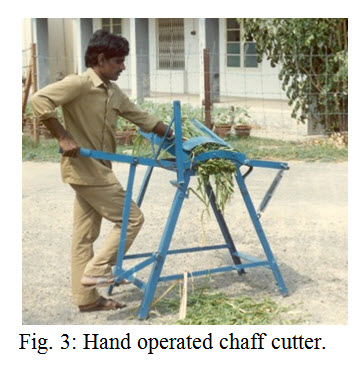
The chaff cutter consists of a feeding tray, curved blade fixed on to a spring loaded lever, anvil which also acts as cutting blade and a suitable frame work (Fig. 3). The cutting action is similar to the shearing machine used in the workshop. The blades are made from medium carbon steel or low alloy steel, hardened and tempered to about 45 HRC. For operation, fodder is fed in the tray pushed by one hand, and the other hand and a leg actuates the curved cutting blade. A thin layer of fodder is spread on the anvil blade and the curved blade progressively shears the fodder into small pieces. It is used to cut chaff, grass, green and dry fodder crops and paddy straw into bits for feeding to animals.
Care and adjustments of hand chaff cutter: Since the hand operated chaff cutter is a simple and useful machine, it is very popular among Indian farmers. In order to get the most efficient operation for a long time; it must be properly installed on a rigid foundation preferably under shed. Many farmers have converted hand chaff cutters into power chaff cutters by using 1 hp electric motor or small engine. The following general procedure of maintenance and lubrication should be followed:
-
Before the machine is put into operation, its gears and bearings should be lubricated.
-
The knives should be sharpened by hand filing. If the cutting edge has become too blunt, it should be sharpened on a grinder to the proper bevel only on one side.
-
The clearance between the knives and the shear plate should be adjusted for the effective cutting.
-
Loose nuts, bolts, and screws should be tightened to avoid accidents.
-
After the day’s work is over, dirt from the gears and bearing parts and moisture from the knives should be wiped off.
-
While the machine is idle, its flywheel should be kept locked so that the children do not operate it.
-
Most of the cast iron parts and particularly the flywheel of the machine are quite susceptible to breakage by hammering, which should always be avoided.
-
The moving parts should be properly lubricated.
Problem 1: Find the capacity of a field chopper with throat size of 25 x 5 cm operating at 50 rpm. The number of knives on cutter head is two and bulk density of material is 500 kg/m3. Length of cut is 2 cm and field efficiency of chopper 70%.
Solution: Using equation 1
C = 60 x 0.7 x 500 x 0.02 x 0.25 x 0.05 x 2 x 50
= 525 kg/h
Problem 2: A small knife chaff cutter fitted with two knifes cuts dry hay at 40 rpm giving 400 kg of cut hay per hour. The throat size of chaff cutter is 20 x 5 cm. The effective distance of centre of throat from flywheel is 20 cm. The blade makes a clearance angle of 10 degrees between the knife support and plane of rotation. Distance of inner edge of throat from flywheel centre is 10 cm. Calculate:
a) Length of cut of chaff
b) Effective density of dry hay, and
Solution:
a) Length of cut of chaff is given by
L = 2 p R tana /N
= 2 p x 10 tan10/2 = 5.5 cm
a) Effective density of dry hay is given by
C = 60 x 10-3 D L W H n N
0.4 = 60 x 10-3 D x 0.055 x 0.2 x 0.05 x 40 x 2
D = 151.5 kg/m3
Conventional Balers
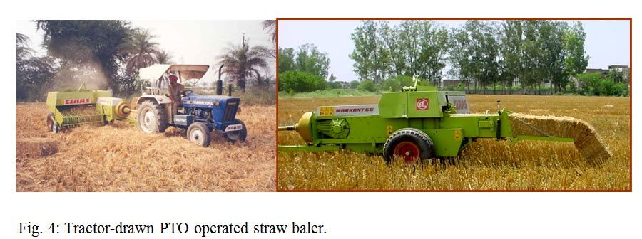
Conventional balers are automatic tying machines with reciprocating plungers those produce bales of rectangular cross-sections. The number of wires or twines placed around each bale classifies them. The three-wire balers commonly used in areas where high percentage of hay is sold and transported commercially. Most field balers are pull-type operated by a tractor, but self-propelled balers are also available commercially. Pull-type balers are available with either a PTO drive or mounted engine type. PTO driven pull-type balers are very common now days (Fig. 4).
Plunger-type field balers have following functional components:
a) A unit to pick-up hay from windrow and elevate it.
b) A conveyor to move the hay to the bale chamber entry.
c) A packer to place the hay in the chamber while plunger is on its retracted stroke.
d) A reciprocating plunger to compress the hay and move it through the bale chamber.
e) Means of applying forces to resist the movement of hay through the bale chamber and thus control the degree of hay compression and the resultant bale density.
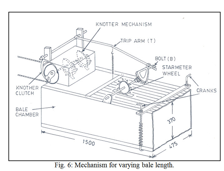
f) An automatic metering device for controlling bale length.
g) means of separating consecutive bales and placing the wires or strings around each bale.
h) Automatic tying devices that operate when the bale reaches the pre-selected length.
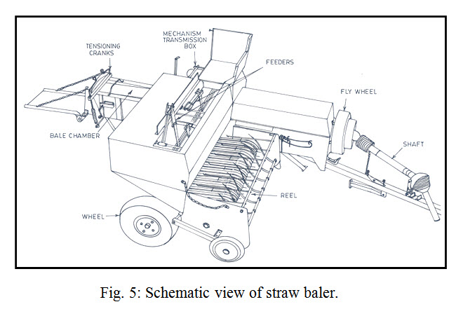
Field balers employ cylinder-type-picking units with spring teeth on cam-controlled tooth bars. The counterbalance springs supports the pick-up mass. The peripheral speed is generally kept higher than the forward speed. Floating cross-conveyor auger and packer fingers push hay into the chamber when the plunger is on its retracting stroke. As the plunger moves on its compression stroke, each new hay charge is compressed until plunger force becomes large enough to move the completed bales along the chamber. On the return stroke of the plunger, fixed wedges and spring-loaded dogs hold compressed hay. The density of bale is affected by the type of material, moisture content and the total resistance that the plunger must overcome in moving the material through bale chamber. One of the problems encountered in baling hay is the change of bale density as the moisture content varies from one part of the field to another or it changes with time. The density of compressed bales can be adjusted by density setting screws provided at exit of baling chamber. The wire is placed across the periphery along the length of bale at two locations. The machine has, therefore, two wire twisters, wire cutting discs and needles. The binding mechanism is put into operation by a clutch actuated by clutch lever, which in turn pressed by a cam mounted on a notched metering wheel. The straw baler can also be used as hay baler.
Baler is also called packing machine which picks up loose hay or straw, Compress it into bales of even size & weight then ties them with twines or wires and finally the completed bale is discharged from the back of the baler to ground. Fig. 4 shows the baler in field operation. Fig. 5 and Fig. 6 shows the schematic view of straw baler and mechanism for varying bale length respectively.
Classification: Baler can either be classified on the basis of power source or on the basis of types of bales.
1. On the basis of power source
PTO operated
Auxiliary engine
Self-propelled baler
2. On the basis of types of bales
Rectangular Bales
Round Bales
Functional Components: Baler mainly consist of following units:-
- Pick Up Unit
- Feeding Unit
- Compressing Unit
- Knotting Unit
- Conveying Unit
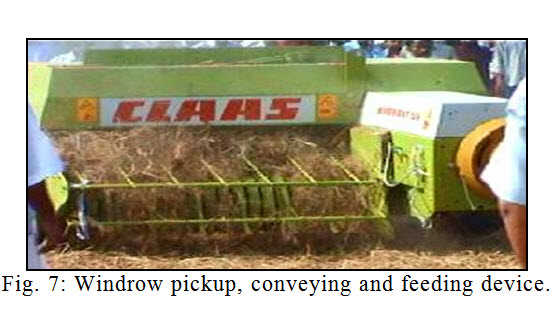
Description of functional components: Most of the field balers employee cylinder type pickup units with spring teeth on cam control tooth bars, loading cross conveyor auger and packer. Windrow pickup, conveying and feeding device is shown in the Fig. 7.
Compressing unit: In the compressing unit firstly feeder teeth pull the hay into bale chamber, plunger compresses the hay into bale chamber and when plunger is at rear position knotting device makes the knot.
Compressing hay and controlling bale density: The plunger, fixed wedges, spring loaded dogs are used to compress hay. Method of controlling bale density is done by squeezing together two sides or all the four sides of the bale chamber at the discharge end. There are two types of the bale tension control devices used which are (i) Automatically controlled hydraulic type; and (ii) Spring type.
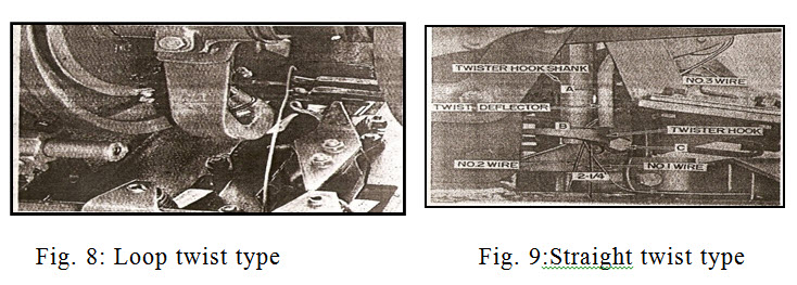
Automatic wire tying devices: There are two types of automatic wire tying devices which are: (i) Loop twist type, and (ii) Straight twist type. Each type has a clamping device that holds the end of wire. When the needle has moved to its extreme penetration position, the clamping device is moved to release wire end that had been held during bale formation then, shear the wire that has been brought by needle and finally clamp the wire from needle which will become held end for next bale. Fig. 8 and Fig. 9 shows the two types of automatic wire tying devices respectively.
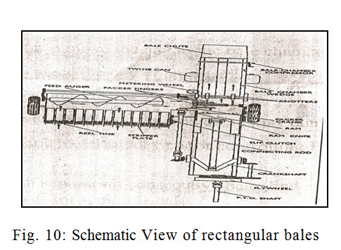
Rectangular bales: The hay lying in the field gets collected by the revolving pick up drum. The pickup tynes rotates in opposite direction to the land wheel. The cross auger rotates continually and delivers the crop to the packer arms or feeder teeth which pull the hay into the bale chamber. Then it`s feed to the high pressure press. The piston of the high pressure press works 69 to 80 stokes per min. and press the hay in compact form. The Ram is fitted with knife blade on straw entrance side which cut the straw when the Ram is in the onward stroke. When the bales take up the shape the tying unit operates automatically and bind the bales at low places. After binding the bales, the binding unit of the baler, throw that on ground. Rectangular bales generally vary from 14" x18" to 16“x18" and 32" to 42" in length. The weight of each bale 15 to 40kg. The Schematic view of baler giving rectangular bales is shown in Fig. 10.
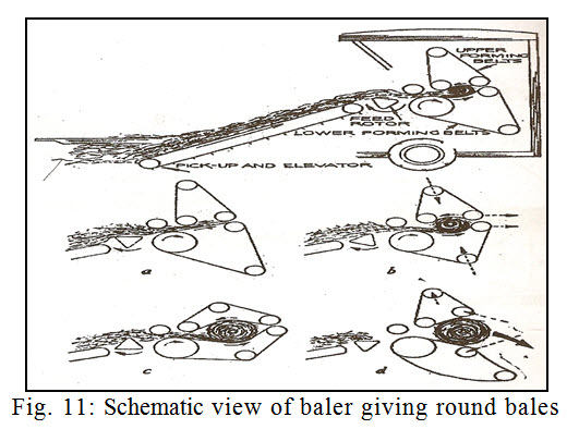
Baler giving round bales: In case of round bales, the pickup lifts the hay from the windrow and carries it between steel compression rollers. Six bands or belts pass over the lower drive roll and also over a trip roll and a tension roll. The upper part of the mechanism consists of six more bands, which passes through a small drive roll, a tension roll and a trip roll. As the bale is rolled, the upper belt arms extend the tension spring and tension increases in the upper belts to squeeze the ball. When the belts have completely extended a relative value, the hydraulic rear gate cylinder opens and triggers the gate bottom to move to the rear until the maximum bale diameter is reached. When the full bale diameter is reached, twine is feed into the bale chamber with the hay. When the bale is twine wrapped, the twine is cut off. Finally the hydraulic controlled gate is raised and the bale is discharged. Most of the round bales are of 1.5 to 2.1 m in diameter and 1.2 to 2.1 m in length. The Schematic view of baler giving round bales is shown in Fig. 11.
Power Transmission: The PTO drive is transmitted through a heavy flywheel to a gearbox. Here a pair of bevel gears put the drive through a 90 degree. A crankshaft on the gearbox output shaft gives the plunger it’s back and fro motion. Drive to pick up, auger, packers and tying unit is also taken from the main gearbox. Most of the drive is by chain and sprockets.
Baler capacities: Baler capacities are affected by:
-
Size of the bales
-
no. of the plunger stokes per min
-
the amount of power available
-
the durability and reliability of the machine
Expected break down in balers:
-
Overloading due to picking up of foreign objects or slogs of hay and careless operation
-
choking due to the excessive clogging of the straw
-
Failure of the machine parts like plunger, fly wheel and bolts
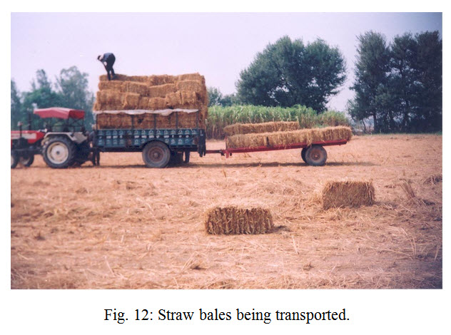
Straw balers can be used either in combine-harvested paddy field or in the combine-harvested rice field where stubble shaver has been used for cutting of standing straw. The forward speed of baler generally varies between 2 km/h to 3.0 km/h. The fuel consumption is in the range of 10-11 l/ha. The field capacity is 0.25 ha/h to 0.35 ha/h. The size of rectangular bales can be varied from 80 x 45 x 45 cm to 150 x 45 x 45 cm and bale weight can be varied from 15 to 45 kg. The number of bales formed may vary from 80 in combine-harvested field and 170 in stubble-shaved field. The bales so formed by the baler may be transported (Fig. 12) to the paper mills or to the location where it can be used for electricity generation.
Hay Stackers
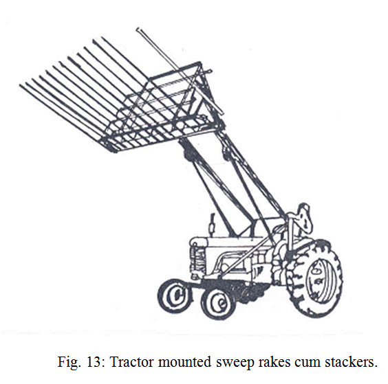
Sometimes hay is stacked in the field rather than stored in the barn. Many types of stackers are built both commercially and locally. For medium-sized stacks, sweep-rake stackers attached to tractor are used (Fig. 13). A new system of stacking hay consists of a windrow pick-up and a compression chamber. The hay is picked up and blown into the chamber in stages where it is compressed with a power packer until the chamber is full. When the compression chamber is full, the stack is transported to storage site and unloaded. Special stack mowers are also available.
Hay Rakes
The use of hay loaders and pickup balers created a demand for a hay rake that makes a loose, fluffy and continuous windrow. Hay rakes can be classified as side-delivery and sweep. Side-delivery rakes are further classified according to the types of reel construction such as cylindrical-reel, parallel bar or side stroke and finger wheel. The reel bars are attached to three spiders and the rake teeth are curved forward near the end to aid in picking up the hay. Most teeth are made of spring steel and have a coiled section next to the reel bar. While in contact with hay, the teeth are held at an angle with the points leading. This gives a pushing with a slight lifting action to the hay. Cylinder-reel side delivery hay rakes are generally available in four types; ground-driven trailing, semi-mounted ground-driven, tractor mounted PTO driven and hydraulic drive.
The parallel-bar or side stroke hay rake may have four to six reel bars attached to two parallel plates or spiders at each end of the reel. The plates are set at right angle to the direction of travel. As the reel revolves, each bar rotates within the bearing mounts to keep the teeth in a vertical position at all times. When a bar approaches its lowest position, teeth come in contact with hay and rakes for a short distance. The next bar follows it. Sweep rake is sometimes called a buck or bull rake. It collects hay from the windrow and transports for short distance to a stationary baler or stack.
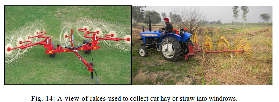
A hay rake is an agricultural rake used to collect cut hay or straw into windrows for later collection. It is also designed to fluff up the hay and turn it over so that it may dry. It is also used in the evening to protect the hay of the dew. The next day a tedder is used to spread it again, so that the hay dries more quickly. A hay rake may be mechanized, drawn by a tractor or draft animals, or it may be a hand tool. The earliest hay rakes were nothing more than tree branches, but wooden hand rakes with wooden teeth, similar in design to a garden rake but larger, were prevalent in the 19th and early 20th centuries, and still are used in some locations around the world.
Mechanical rake known as the side delivery rake usually had a gear-driven or chain-driven reel mounted roughly at a 45-degree angle to the windrow, so the hay was gathered and pushed to one side of the rake as it moved across the field (Fig. 14). A side delivery rake could be pulled longitudinally along the windrow by horses or a tractor, eliminating the laborious and inefficient process of raising, lowering, and back-and-forth raking required by a dump rake. This allowed for the continuous spiralling windrows of a farm hayfield. Later versions of the side delivery rake used a more severe transverse angle and a higher frame system, but the basic principles of operation were the same. Later, a variety of wheel rakes or star wheel rakes were developed, with 5, 6, 7 or more spring-tooth encircled wheels mounted on a frame and ground driven by free-wheeling contact as the implement was pulled forward.
Desirable characteristics of hay rakes: The following are the some of the desirable characteristics of hay rakes:
a) The amount of leaf loss due to shattering.
b) The amount of hay missed.
c) The amount of trash, dirt etc. put into windrows.
d) Uniformity and continuity of windrow.
e) Amount of leafy portion in centre of windrow and stems toward the outside.
The amount of leaf loss is affected by the distance the hay is moved from swath into windrow, average hay velocity, type of hay moving action i.e. rolling, lifting or dragging and periodic impact of rake teeth upon the hay. Average hay velocity is affected by forward speed and high forward speed increases the leaf shattering.
The type of side delivery rakes are Reel-type units and Finger-wheel units. All reel type rakes were of the cylindrical-reel type. The tooth rotated in parallel positions in planes perpendicular to the reel axis, similar the pickup reel. The reel heads are set at a horizontally acute angle from the reel axis but in parallel planes. The tooth bar ends are shaped so the axes of the tooth-bar bearings are perpendicular to the planes of the reel heads. This arrangement automatically maintains the teeth in parallel positions as the reel rotates. The horizontal path of any tooth is in a plane parallel to the reel-head planes. Thus the horizontal movement of the teeth with respect to the rake can be 85° to 90 ° from the direction of forward motion.
Finger-wheel units: As finger rake has a series of individually floating, ground-driven wheels set at an angle to the direction of motion and overlapping each other. Each wheel is partially counterbalanced with a tension spring and has spring teeth around the periphery that operate in light contact with the ground. The floating feature allows the rake to adjust itself to the contour of surface irregularities such as irrigation levees or terrace channels. Wheel tooth-tip diameters are usually about 1.5 m.
Last modified: Wednesday, 11 September 2013, 11:12 AM