Site pages
Current course
Participants
General
MODULE 1. PRINCIPLES AND TYPES OF CUTTING MECHANISM
MODULE 2. CONSTRUCTION AND ADJUSTMENT OF SHEAR AND...
MODULE 3. CROP HARVESTING MACHINERY
MODULE 4. FORAGE HARVESTING, CHOPPING AND HANLING ...
MODULE 5. THRESHING MECHANICS, TYPES OF THRESHES, ...
MODULE 6. MAIZE HARVESTING AND SHELLING EQUIPMENT
MODULE 7. ROOT CROP HARVESTING EQUIPMENT
MODULE 8. COTTON PICKING AND SUGARCANE HARVESTING ...
MODULE 9. PRINCIPLES OF FRUIT HARVESTING TOOLS AND...
MODULE 10. HORTICULTURAL TOOLS AND GADGETS
MODULE 11. TESTING OF FARM MACHINES, RELATED TEST ...
MODULE 12. SELECTION AND MANAGEMENT OF FARM MACHIN...
LESSON 11. GRAIN COMBINES, TERMINOLOGY, ADJUSTMENTS, LOSSES, TROUBLE SUITING
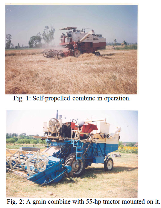
A combine is farm machine that combines the reaper and thresher to harvest the standing crop, thresh it and clean the grain from straw in one operation. According to source of power used combines may be classified as self-propelled combines (Fig. 1) and tractor operated (Fig. 2) or trailed type combine. Self-propelled combines use a propelling power source to do various operations. In tractor operated combine, the power is being optioned through detachable tractor. Only at the time of harvesting tractors are attached and rest of the times it can be used for other farm operations.
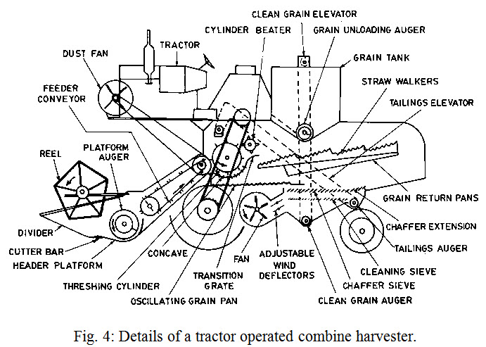
The present day combine harvesters are being mostly used for harvesting two major crops namely wheat and paddy. Other crops can also be harvested with combines like, sunflower, maize, soybean, pulses etc, with slight changes in the combine. A combine harvester consists of header platform, reel, cutter bar, crop divider, platform auger, feeder conveyer, cylinder, concave and grate, fan, chaff sieves, straw walkers, grain sieves, grain auger, tailing auger, grain elevator, grain container and grain unloading auger (Figs. 3 and 4).
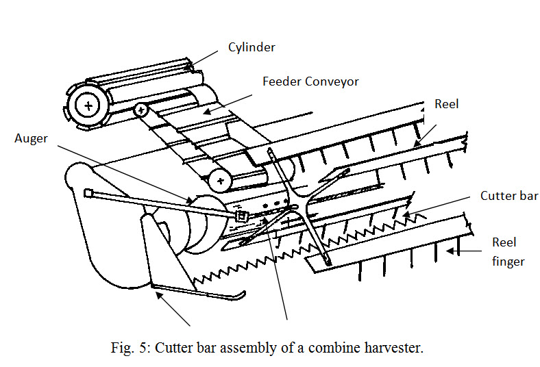
Cutter bar assembly: The cutter bar assembly comprises of finger bar, fingers, knife guides, wearing plates, outer shoes and main shoes that is non-reciprocating part of the cutting mechanism (Fig. 5). The cutting unit of a combine uses a mower type cutter bar. The knife on the combine uses serrated edge sections. The length of stroke is often longer and sometimes the section passes over two guards in one stroke. The knife section edge is serrated to help keep the straw from slipping while it is being cut. The serrated sections cannot always be sharpened and are generally replaced when they become dull. The cutting platform of combine should be adjustable to operate at a height, from 7.5-90 cm above the ground level. The platform is also provided with a reel and a canvass carrier.
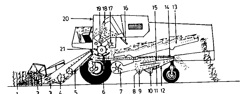
Fig. 3: Details of a self-propelled combine.
1. Crop divider 2. Reel 3. Knife 4. Auger conveyer
5. Feeding conveyer 6. Concave 7. Blower 8. Grain auger
9. Grain elevator 10. Ear auger 11. Grain collector 12. Ear collector
13. Straw walker 14. Rake 15. Sieves 16. Deflector
17. Straw guide drum 18. Tank filling auger 19. Tank auger 20. Grain tank
21. Threshing cylinder
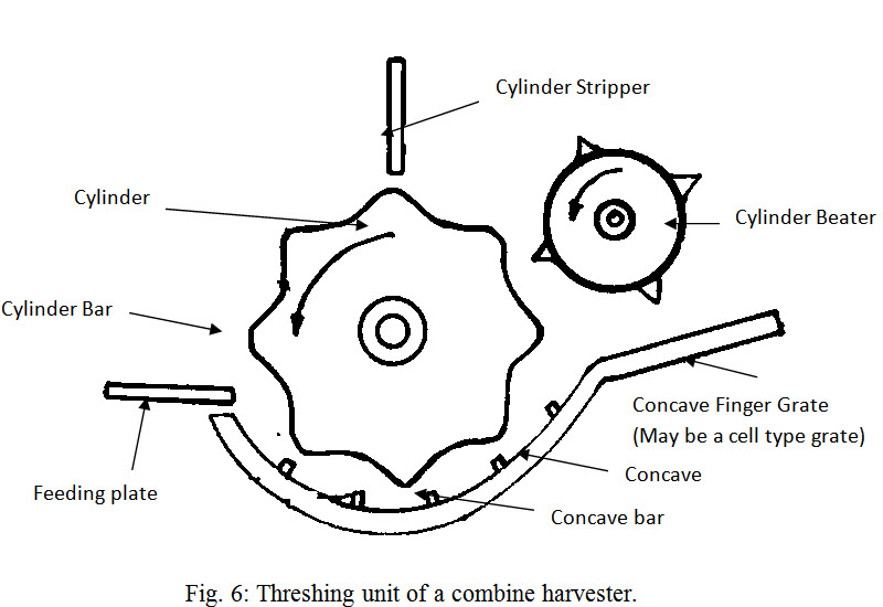
The reel consists of a number of wide slats or arms with battens arranged parallel to the cutter bar to hold the crop being cut by the knife and to push and guide it to feeder conveyor auger. The reel may be of spring type or slat type. Its height and speed are adjustable. A clearance of about 12.5-25.0 cm between the reel and cutter bar is suitable for all purposes. The reel gets power through suitable gears and shafts. The reel revolves in front of cutter bar while working in the field. The cut crop is then fed to cylinder and threshing takes place between cylinder and concave units of machine. The basic components of threshing unit of combine are similar to that of power thresher (Fig. 6). The threshed material then moves to oscillating straw walker, which separate the grain from straw. The amount of grain not separated at any point along the walker length can be determined by
RL = e-b L
Where,
RL = decimal fraction of the grain onto the walker that is not separated at
distance L
L = distance along the walker from the effective point of delivery of material
onto the walker
b = constant (function of feed rate, grain-straw ratio, crop variety and
condition, walker design etc.)
If the walker is divided into uniform length increments, the amount of seed separated in any increment is a constant percentage of amounts of seed onto that increment. The effective delivery point on the walkers is 150-230 mm from the front end of walkers. If walker loss for a given crop condition and feed rate and seed rate onto the walker are known, the value of b can be calculated.
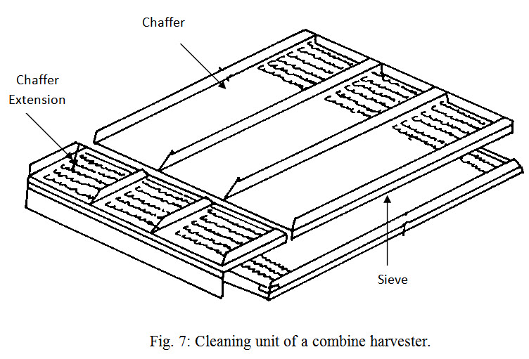
The cleaning unit (Fig. 7) consists of a number of sieves and fan cleans the grain. The un-threshed grains pass through tailing auger and go to cylinder for re-threshing. The grain passes through an elevator and collected in a hopper or directly unloaded to the trailer. The fan is adjusted such that the chaffs are blown off to the rear of the machine. The size of the combine is indicated by the width of cut it covers in the field. Some adjustments are always necessary on combines before being used for harvesting of crop. These adjustments are:
Cutter bar height: The height of the forward tip of any knife section above the plane on which the combine is standing expressed in millimeters, is called cutter bar height. This height is adjustable and ranges from 75-900 mm. The crop is cut just low enough to cover nearly all the heads. If straw is to be saved cutting may be at a lower height.
Reel speed: It is essential to keep the reel speed in proper relation to the forward speed of the combine. If reel speed is more, grain shattering from heads occurs. If reel speed is lower then grain may fall on the cutter bar. Hence speed of reel should neither be more nor less. The speed of reel can be adjusted by changing the reel-driving sprocket.
Feeding: The tension of upper and lower feeder canvass is kept tight enough to prevent slippage. If they are too tight, there will be wastage of power and excessive wear will take place.
Cylinder-concave clearance: The gap between the tip of the cylinder to inner surface of the concave is called cylinder-concave clearance. The method of adjusting clearance varies with different machines. In some of the combines, raising or lowering the cylinder changes the cylinder-concave clearance, whereas, in other cases, the height of concave assembly is adjusted to change the cylinder-concave clearance. Close clearance results in more breaks up of the straw, which decreases the effectiveness of separating and cleaning unit. The spacing between concave and cylinder at front is usually adjusted from 2-30 mm and at rear 2-18 mm. With close type concave, the normal setting of concave is closer to the cylinder at the front rather than rear. With open type concave, the concave is normally closer at rear than at front.
Chaffer opening: This is upper sieve on which grass and chaff mixture falls for initial cleaning. The sieve is oscillated so that grains pass through chaffer openings and chaff and un-threshed materials thrown at rear of the machine. The chaffer opening should be provided such as to float chaff away without blowing out grain, but coarse heavy material should be retained and discharged at the rear.
Shoe sieve opening: The opening should be just large enough to permit free passage of grain. Adjustable shoe sieve with smaller lips and openings are the most common.
Tailing gate height: Tailing gate is a device provided at the rear of the cleaning unit to prevent un-threshed material from passing out of the combine. It can be adjusted by raising the tailboard at the end of the chaffer extension if necessary to prevent threshed grain from being blown out.
Platform: The platform holds the cutter bar and feeding mechanism.
Cutting platform auger moves the cut grain to the centre of the platform where the retractable fingers feed the crop into the feeder conveyer.
Feeder convener: The feed conveyor or feed rake is designed to feed the crop in a steady even flow into the threshing unit.
Feeder beater takes the crop from the feed conveyer and feed it uniformly to the threshing unit.
Threshing unit: The function of this section of combine is to thresh the grain from the heads. This is done by passing the grain between a rapidly revolving cylinder and a stationery surface underneath which is called the concave. The grains are separated from the pods by impact, rubbing or squeezing actions between cylinder and concave.
Threshing cylinder: The threshing cylinder may be of different types
-
Rasp bar type - having corrugated bars
-
Angle bar type - right angle bar with rubber facing
-
Spike tooth type - pegs or spikes on it.
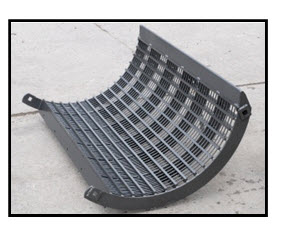
Concave: The concave is the stationary part that the cylinder works against in the threshing action. The concave is a grate composed of rods and bars or wires. It is at the concave grate and finger grate that as much as 90% grain is separated from the crop. The separated grain falls through the grate on to the shoe pan where it is delivered to the cleaning unit. The straw and the remaining grain pass on to the separation unit.
Cylinder beater: The beater behind the cylinder slows down the material coming from the cylinder tears apart the straw and delivers the material to the straw rake or straw walker. The beater helps in cleaning the straw from the cylinder thus preventing cylinder wrapping and feedback.
Separating Unit: The separating unit agitates the straw after it comes from the threshing unit. This shakes out the loose grain remaining in the straw and delivers it to the cleaning unit. The straw is carried out of the combine by the rack.
One piece straw rack: The straw rack is a one piece unit with risers pointed toward the rear of the combine. The straw rack is mounted on cranks located at the front and rear which give it an oscillating motion. As the crank moves rearward and upward the straw is tossed up and to the rear. As the rack returns forward and downward the straw stays in mid air for a short time and then falls in to the section of the rack nearer the end of combine. In this way the straw moves step by step out of the combine.
Walker type straw rack: Some large combine may use a walker type straw rack which operates on the same principle as the rack. The straw walker has three or more narrow sections placed side by side. Each section is mounted on multiple throw cranks located at the front and rear. The crank throws for section are equally spaced around the circle of rotation thus the sections do not operate as a unit as one piece rack does.
Grain return pan: It is located under the straw rack. It catches the grain as it falls through the rack and moves forward to the grain pan.
Grain return conveyor: In place of grain return pan some combines will use a conveyor to catch the grain and move it forward.
Grain pan: The grain pan is located under the forward part of straw rake behind and below the cylinder. Its function is to catch the grain from the concave and cylinder grates and from grain return pan or conveyor for delivery to the cleaning unit.
Cleaning unit: The function of cleaning unit is to separate the clean grain and deliver it to the grain tank, return tailings to the cylinder for re-threshing, and move the remaining material out of the combine. This is accomplished by means of gravity and air blast.
Adjustable chaffer: The adjustable chaffer act as a sieve. It is made up of a series of cross pieces mounted on rods and fastened together so they can be moved at the same time to adjust the size of the openings.
Chaffer extension: This is an extension of chaffer having adjustable lips. The un-threshed portion of gain heads fall through the chaffer extension into the tailing anger.
Sieve: The sieve likes chaffer except that the lips and openings are smaller. The final job of cleaning is done here.
Cleaning fan: The fan furnishes a blast of air. The strength of air blast is controlled by wind board. The function of the air blast is to keep the material alive on the chaffer and sieve. The air blast should be strong enough to lift the chaff slightly off the chaffer and sieve, but not strong enough to blow grain out of the combine.
Tailboard: The tailboard keeps the un-threshed material from being carried out of the rear of the machine while still allowing the chaff to in blow cut. It may be raised or lowered as needed.
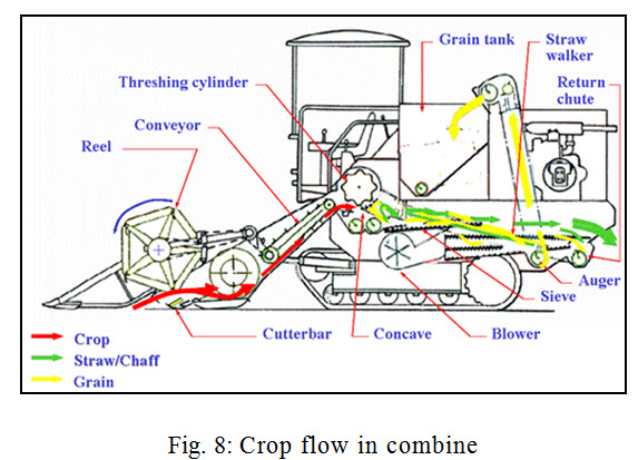
Material Handling: The grain auger collects the clean grain and angers it to the clean grain elevator which delivers the clean grain to the grain tank. Crop flow in combine is given in Fig. 8.
Last modified: Thursday, 12 September 2013, 4:59 AM