Site pages
Current course
Participants
General
Module 1. Introduction about design and developmen...
Module 2. Study of special design features of trac...
Module 3. Study of basic design parameters for tra...
Module 4. Selection of different mechanical power ...
Module 5. Study of tractor steering and suspension...
Module 6. Design and analysis of tractor hitch sys...
Module 7. Design of a tractor hydraulic system
Module 8. Study of electrical, electronics and gui...
Module 9. Ergonomics, controls and safety features...
Module 10. Tractor testing
Module 11. General revision
Appendices & References
Lesson 16. Study of tractor hydraulic systems and controls
1. Introduction
Hydraulic System of a Tractor is provided to enable the tractor to raise or lower heavy implements as per requirements and to control implement depth during field operations with minimum efforts.
2. Fundamentals and components for fluid power transmission
Fluid power is based on the principle of Pascal’s law which states that pressure applied to a fluid is transmitted equally in all direction. Hydraulic Fluid is assumed as incompressible. The fluid pressure controls the force of output. (P= F/A= force/area). The fluid flow controls the speed of output. The basic components of fluid power transmission are as follows:
Reservoir
Pump
Motor
Cylinder
Valves
Fittings and tips
Lines and Hoses
Hydraulic oil
i. Reservoir
In the modern tractors transmission case also serves as hydraulic reservoir. The reservoir is vented to atmosphere to accommodate changing oil levels. The air vent is provided with a filter to prevent dirt/dust entry into the reservoir. The hydraulic reservoir stores non-pressurized hydraulic fluid, typically hydraulic oil. This fluid is the lifeblood of the hydraulic system. The hydraulic oil also travels through a filter that collects impurities. The metal walls of the reservoir cool the fluid by allowing heat to escape. The reduced pressure in the reservoir also allows trapped or dissolved air to escape from the fluid. Generally, the size of the reservoir should be 3 times system capacity, or 1.5 times the pump GPM rating. The reservoir must also have adequate surface area to allow heat to disperse.
ii. Pump
Hydraulic pump transfer the fluid from the reservoir to the hydraulic system. This transfer raises the energy level of the fluid by increasing its pressure. One-stage, or single-stage, pump has only one maximum pressure and one flow rate. Single-stage pumps are typically attached to the crankshaft or PTO shaft on a farm tractor. Applications for a single stage pump include back hoes and manure loaders. A two-stage pump will first produce high volumes of fluid, moving the cylinder in and out quickly. When the pump receives resistance, a second set of gears will produce high pressures for lifting or splitting. However, the volume of fluid will drop considerably during this stage. This mechanism has many practical applications. For example, in log splitters equipped with a two-stage pump, in stage one, the rod travels faster up the cradle until the rod starts to split the wood. At that point, the speed slows but the force increases.
iii. Motor
The motor provides the power source for the pump. The high-pressure fluid acts upon the rod and piston within a hydraulic cylinder. Each stroke of the cylinder converts the fluid power (pressure) into work (mechanical force). The reservoir oil level falls while the rod and piston are extending, when the rod and piston retract, the fluid returns to the reservoir.
iv. Cylinder
In a single-acting cylinder, pressure is applied to one side of the piston. Therefore, work occurs in one direction only. The cylinder returns to its original position under the weight of the load (or by means of a manual lever). In a double-acting cylinder, pressure can be applied to either side of the piston. This allows work to occur in either direction. Tie-rod cylinders are held together by four rods. They cost less than welded cylinders and are easy to repair. On a welded cylinder, the fixed end is welded in place, adding strength and durability for high-pressure applications such as log splitters. If cylinders must compress air bubbles, the efficiency of the system is reduced.
v. Valves
There are two types of valves, directional control valves and pressure relief valves. Directional control valves manage the flow path of the fluid in the system. Pressure relief valves protect the system plumbing and components against pressure overloads. They also limit the output force exerted by rotary motors and cylinders. These valves open whenever the pressure goes beyond the set value, allowing oil to flow back into the reservoir. The fluid travels from one component to the next within a hydraulic system through a hydraulic hose.
Directional control or flow control valves used to control fluid flow in the system (speed of actuators). Check valve allows fluid flow in one direction, no flow in the other direction. Needle valve- acts like variable orifice to restrict flow. Pressure compensated valves- automatically adjust the fluid flow to compensate for pressure variations in the system. Ball valves and Spool valves are used for controlling the flow of fluid.
Pressure control valves are used to control pressure in the system. These are provided to protect the components within hydraulic circuit from damage from excessive pressure. These are also called as safety relief valves. Relief valve is essential for safety as it sets maximum pressure in the system. The most basic type is a poppet held against a cone seat by spring force. Pilot operated pressure regulator valve provides fast action to respond to flow changes. Other common types of valves are: Pressure reducing, sequence, unloading valves etc.
vi. Fittings and Tips
NPTF and JIC fittings both prevent leakage on the ports of hydraulic components. However, NPTF or “dry seal” taper pipe threads do this by using the resistance of the male to female thread taper. JIC or “straight” threads use an O-ring. JIC and NPTF fittings cannot be used interchangeably. However, special adapters can be used to convert from one type of fitting to another. Tractor Supply’s product catalogue for a complete listing of fittings and adaptors can be consulted.
There are three types of I.S.O. tips. All three are interchangeable with each other and universal, except as noted below. The I.S.O. tip with ball was the first standard, universal tip in the marketplace. It seals with a metal-to-metal seat. This seal tends to “weep” when disconnected, but it is still the most widely used tip in the industry. The I.S.O. tip with poppet has the same basic design. However, this tip seals with an O-ring that presses together with the poppet to form a tight, 360-degree seal. This “soft seal” reduces fluid loss. In the future, this will be the choice of OEM manufacturers. The I.S.O. tip with pressure relief poppet has a secondary poppet in the tip. When pressure builds up in the hose, this secondary poppet allows pressure to be displaced to the coupler. The tip can then connect without pressure. Certain OEM designs that predate the introduction of I.S.O. tips require the use of OEM old-style tips. These tips and couplers are unique to each manufacturer, and cannot be interchanged. Specific conversion adapters are required for these machines to accept I.S.O. tips.
Galvanized and brass fittings do not meet the psi ratings of hydraulic systems. The metal tends to flake. This flaking can contaminate the oil and damage the hydraulic pump.
Teflon tape may flake. This flaking can contaminate the oil and damage the pump. Warranties are typically voided by using Teflon tape. Use a hydraulic-rated liquid Teflon sealant instead.
vii. Lines and Hoses:
The various components of the brake hydraulic system are connected through lines and hoses. Lines are made of steel and hoses are made of braided rubber. Lines connect the stationary parts of the hydraulic system and hoses connect the parts which move in relation to each other. The size of the pipe, tubing, or hose in a hydraulic system is very important. If the hose is too small, the oil flows at a high rate of speed. This generates heat, which means that the fluid is losing power. If the hose is too large, the time and cost of installation may be too high. A 2-wire hose is recommended for applications above 126.55 kg/cm2 (1800 psi). However, specifications vary by manufacturer, so read product packaging for specific application suggestions and psi ratings.
viii. Hydraulic Oil
Hydraulic oil is petroleum oil refined for use in hydraulic systems. This oil typically has additives to prevent rust and minimize foaming. The term “hydraulic fluid” is often used interchangeably to mean oil or any other fluid within a hydraulic system. Using the incorrect fluid can harm seals and cause the system to break down. Oil contaminants can increase operating temperatures and damage components. Change the oil and filter regularly to prolong the life of the system. Viscosity is most important property of hydraulic fluid. Generally, fluid viscosities are recommended between 12 to 48 MPa by the manufactures at operating temperature of pump. Otherwise, the performance of the pump will be affected considerably. Each tractor manufacturer specifies the hydraulic fluid that will meet requirements of both transmission and hydraulic system. The oil temperature should be kept below 60°C to reduce oxidation of oil. Additives are needed to reduce wear in gear/vane type pumps above 7 MPa operating pressures.
3. Types of Hydraulic Systems:
Two types of hydraulic system are used “open center system” and “closed center system” refer to two methods of reducing the pressure on the pump, which minimizes wear and tear. Hydraulic power is controlled by directional flow valves. Valves provide methods to control one or several flow paths from a single pump with relative ease. These valves regulate the rate of flow that is permitted to operate individual hydraulic actuators. They direct the flow path of fluid in two ways.
Open center system: Open systems were common and were used on most of the earlier tractors. When an open system is in neutral, an open center valve connects all lines directly back to the reservoir, bypassing the pump. The pump is always pumping, allowing a constant flow of oil without building pressure.The valves allow fluid to flow through the center and return to reservoir when the system is in neutral.A constant flow pump is generally used.
The open-centre system was the first type used on farm tractors, and even today it is most commonly used. In this type of system a valve ‘V’ is used to direct the fluid to a cylinder, ‘C’. The line diagram of open loop system is given in Fig. 16.1.
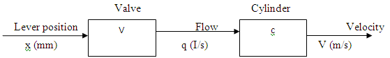
Figure 16.1: Open loop hydraulic control
The transfer function of valve V is the ratio of output ‘q’ (fluid discharge, I/s) to input ‘x’ (control lever displacement, mm) i.e. q/x and the transfer function of cylinder ‘C’ is ratio of output ‘v’ (velocity of piston/s) to output ‘q’ (pump discharge, I/s) i.e. v/q. The overall transfer function of the system can be combined simply by multiplying V X C as given below:
![]() ... (16.1)
... (16.1)
In this type of system the hydraulic cylinder may have a stroke control device that returns the fluid to sump when cylinder reaches the end of stroke. At the end of stroke pressure builds up, causing the valve to return to neutral position. In most cases the operator is quite capable of being a part of control system by sensing (seeing) when the cylinder has reached the desired position, at which point the operator returns the valve control lever to neutral position.
Closed center system: Closed systems are common on modern farm equipment, including most of tractor models. When a closed system is in neutral, the closed center valve blocks the flow of oil from the pump. The oil travels instead to an accumulator, which stores the oil under pressure. The valves allow no fluid to flow through the center when the system is in neutral. A variable flow pump is generally used, which stops pumping when the valve is closed.
In some tractors closed- centre systems are used which employs piston type pumps. Such a system may have a feedback loop. In correctly designed system, when valve ‘V’ and cylinder ‘C’ are into closed loop system, the operator can forget about the control. F is now in the feedback loop. The velocity, ‘V’ of the cylinder can now be “fed back” to the valve ‘V’ by means of single ling device, F, through the summing junction so as to correct the position of the valve. This system provides a rapid response to the loads. The line diagram of closed loop system is given in Fig. 16.2
Lever Valve Cylinder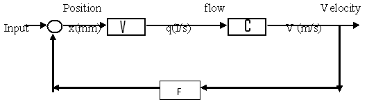
Figure 16.2. Closed loop hydraulic control
Overall Transfer Function (O/I): Overall transfer function of closed loop is given by
![]() ... (16.2)
... (16.2)
Where, V= valve in which the input is the motion of spool (x) and output is fluid flow rate (q). The output/input ratio of valve is also known as flow gain, L/s/mm.
C = dynamic behavior i.e. Velocity of cylinder (v) of the system (Cylinder + hydraulic oil + masses attached to the cylinder).
F = feedback loop force (draft sensing force), which might be either a mechanical linkage attached to an “error bar” or pressure line to sense the load on, or position of the output of the cylinder.
4. Hydraulic control in tractor
i. Automatic hydraulic control
This is also known as an automatic control or feed back system. This compares the output signals to the input signals and uses the difference to change the output. These can be open loop control system or closed loop control system. The main difference between the two systems is that the open centre system maintains a constant flow of oil, and the closed system maintains a constant pressure when not in use.
ii. Automatic position control system
Automatic position control system is normally associated with a three point hitch system. It provides automatic control of an attached implement and allows the operator to pre select and to position the implement as controlled by the hand control lever. The relative position of hand lever and hydraulic cylinder are always identical. Within the limit of the valve controlling the maximum pressure, the hydraulic cylinder will automatically move the implement to its predetermined position and maintain it there, regardless of any leakage in the system. This system is not used with a remote cylinder.
iii. Automatic draft control system
Automatic draft control system will automatically raise or lower the implement as the draft of attached implement increases or decreases. The position of hand control lever, in effect, establishes the draft to be maintained.
The sensing device which actuates the hydraulic system to lower or raise the hitch system is located on either the lower links or upper link, depending upon the size of tractor. The load sensing system senses the load and sends a message to the pump causing it to provide just enough pressure to overcome the load. Under no-load condition, it works under less pressure. Regulation of draft sensing mechanism is given in Fig. 16.3 and it is calculated as given below:
![]() ... (16.3)
... (16.3)
Where,
Fr = Average force to start hitch to raise
F1 = Average force to start hitch to lower
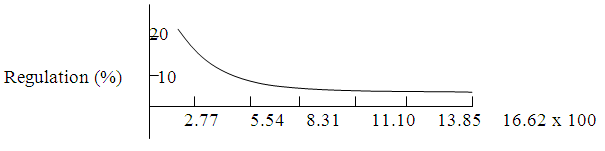
Figure 16.3. Regulation curve for draft control by sensing force in the lower link
Maintaining desired fluid pressure in the system requires power from the engine, just as power is required to maintain constant flow in open-centre system. The main advantage of load sensing system is reduction in power consumption by the pump. However, this system requires an extra line to sense the load and relay message to the pump which adds to the system cost.
Last modified: Monday, 7 April 2014, 7:19 AM