Site pages
Current course
Participants
General
Module 1. Introduction about design and developmen...
Module 2. Study of special design features of trac...
Module 3. Study of basic design parameters for tra...
Module 4. Selection of different mechanical power ...
Module 5. Study of tractor steering and suspension...
Module 6. Design and analysis of tractor hitch sys...
Module 7. Design of a tractor hydraulic system
Module 8. Study of electrical, electronics and gui...
Module 9. Ergonomics, controls and safety features...
Module 10. Tractor testing
Module 11. General revision
Appendices & References
Lesson 18. Design of main components of a hydraulic System
The hydraulic system of a tractor mainly consists of pump driven by tractor engine or power train, hydraulic cylinder, control valves and implement lifting mechanism. Design of these major components is explained below
1. Pump Design
Pumps convert mechanical power to fluid power. Hydraulic pumps which are mainly used are gear type, roller vane type or axial piston variable flow type. The pressures developed by three main types of hydraulic pumps are as follows:
- Fixed gear/vane pump : Pressure up to 10.3 MPa
- Pressure balanced gear/vane pump : 13.8-24.1 MPa
- Pinion type pump : 27.6-34.5 MPa
The common speed of operation of pumps ranges from 3000 to 5000 rpm.
Fluid Power of Pump (Wf )
The fluid power of pump ( Wf ) is given by
![]() ... (18.1)
... (18.1)
Where,
Wf = fluid power, kW
Q = pump discharge, 1/m
P = pressure across the pump, MPa
Shaft Power of Pump
The shaft power of pump (Ws) is given by
![]() ... (18.2)
... (18.2)
Where,
Ws = shaft power of pump, kW
T = input shaft torque, N-m
N = shaft speed, rpm
Also,
![]() ... (18.3)
... (18.3)
Where,
nm= mechanical efficiency or overall efficiency of pump.
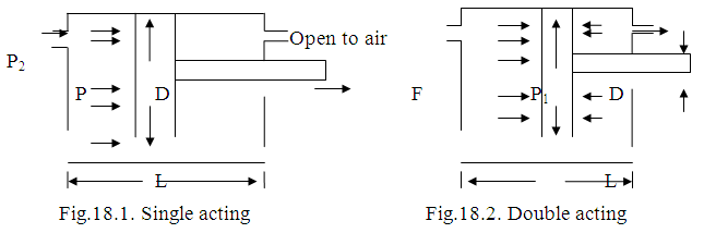
Actuator – linear: Converts fluid power to linear mechanical power. Single acting and double acting hydraulic cylinders are given in Figs. 18.1 and 18.2.
Force in the cylinder is given by
![]() ... (18.4)
... (18.4)
![]() ... (18.5)
... (18.5)
Where, Fe= extension force in the cylinder, N;
Fre = retraction force in the cylinder, N
P= fluid pressure in actuator, N/mm2
Ac = cross sectional area of ram, mm2
A r = cross sectional area of rod, mm2
Where, V = speed of ram is cylinder, m/s.
Theoretical discharge of hydraulic pump is given by
![]() ... (18.6)
... (18.6)
Where,
Dp = volume of displacement of pump in one revolution
N = pump speed, rpm
For plunger barrel type pumps, the discharge is given by
![]() ... (18.7)
... (18.7)
Where, A= area of plunger, cm2
L= length of stroke, cm
N= pump speed, rpm
The actual discharge of hydraulic pump is given by
![]() ...(18.8)
...(18.8)
For plunger barrel type pumps
![]() ... (18.9)
... (18.9)
Where,
ηv = volumetric efficiency of the pump, and is dependent on internal leakage and compressibility of the oil.
Pump Torque (Tp)
The pump torque ( Tp ) is given by
![]() ... (18.10)
... (18.10)
Where,
Tth = theoretical input torque, N-m
P = pump outlet pressure minus pump inlet pressure (bar).
The actual pump torque ( Tp) is given by
![]() .. (18.11)
.. (18.11)
Where,
ηt = torque efficiency of pump, %.
Input or Shaft Power (Ws)
The input or shaft power (Ws) of hydraulic pump is given by
![]() ... (18.12)
... (18.12)
Ws = input or shaft power in kW
T = input shaft torque, N-m
N = shaft speed, rpm
Hydraulic/ Fluid power of pump (Wf)
The Hydraulic/ Fluid power of pump (Wf) is given by
![]() ... (18.13)
... (18.13)
Where,
Q = actual pump discharge, 1/m
P = pressure across the pump, MP
Also ![]() ... (18.14)
... (18.14)
Where,
Q = actual pump discharge, 1/s
H = Head, m
Overall Efficiency of Pump ( ηm)
Overall Efficiency of Pump (ηm ) is given by
![]() ... (18.15)
... (18.15)
2. Flow Control Valves
It is used to control fluid flow in the system (speed of actuators). Check valve allows fluid flow in one direction, no flow in the other direction. Needle valve- acts like variable orifice to restrict flow. Pressure compensated valves- automatically adjust the fluid flow to compensate for pressure variations in the system. Ball valves and Spool valves are used for controlling the flow of fluid.
Following orifice equation can be used to calculate the flow rate (Q) at a given pressure drop across the orifice.
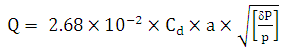 ... (18.16)
Where,
Q= fluid flow rate through control valve, 1/m
Cd = coefficient of discharge, dimensionless
a = area of cross section of orifice of control valve, cm2
σp= pressure drop across orifice, MPa
p = density of fluid, Kg/1
Velocity of fluid flow though the orifice is calculated by following equation
Vo = Q/6a ... (18.17)
Where, V o = velocity of fluid flow though orifice, m/s
3. Lines – pressure, return and intake
Hydraulic lines are used to convey the fluid to remote locations under pressure and dissipate heat developed in the system. The lines should be strong enough to with stand the fluid pressure developed during operation and their size should be such that the pressure drop is minimum. Rigid lines are made of steel while flexible are made from reinforced rubber. Wall thickness of conduit pipe used for fluid pressure lines is calculated based on maximum pressure and hoop stresses developed that would cause failure of conduit pipe along a line parallel to its centerline. It is given by
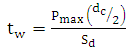 ... (18.18)
Where, tw = wall thickness of conduit pipe, cm
Pmax = maximum allowable pressure, MPa
dc = conduit diameter, cm
Sd = Design stress for the pipe line, Mpa
4. Hydraulic Cylinder
Hydraulic cylinder converts fluid power into linear mechanical force which can be used for lifting/lowering of implements attached to the tractor and control depth of operation in the field. According to fluid flow and forces acting and specific application, the hydraulic cylinders can be classified as:
1. Single acting 2. Double acting
3. Double acting double rod 4. Telescoping and
5. Cushioned top type
Single acting hydraulic cylinders are most commonly used in hydraulic systems of tractors. Single acting type and double acting type hydraulic cylinders
Fluid force acting in cylinder (F)
Neglecting inertia force in the hydraulic cylinders, hydrostatic force transmission is given by
![]() ...(18.20)
...(18.20)
And A1 = (π/4) D2p and A2 = (π/4) (D2p - d2p) ... (18.21)
Or ![]() ... (18.22)
... (18.22)
Where,
P1, P2 = hydraulic pressure, MPa
Dp = piston diameter, cm
dr = rod diameter, cm
S = stroke, cm
A1= piston area of the cap end, cm2
A2= piston area at the rod end, cm2
F = Force or load moved by hydraulic cylinder, kN
In case the return oil line from the rod end is connected back to reservoir at atmospheric pressure, then the piston is extending and
![]() ... (18.23)
... (18.23)
When the supply is to the rod end and the cap end is vented to atmosphere, the piston is retracting. Then,
![]() ... (18.24)
... (18.24)
Speed of rod movement (V)
The speed of piston rod in cylinder is obtained by dividing the volume of fluid flow into the cylinder by the cross sectional area of cylinder bore as under:
Q = 6 AV ... (18.25)
Where, Q= volume of fluid flow, litres/min
A = cross sectional area, cm2
V = velocity of piston, m/s
Power developed by the actuator (Wa)
The power developed by hydraulic cylinder in kW is given by
Wa= Fe. V/1000 ... (18.26)
Where, Fe = Force developed by piston during extending, kN
V = speed of ram in cylinder, m/s
Last modified: Monday, 7 April 2014, 7:35 AM