Site pages
Current course
Participants
General
Module 1. Introduction about design and developmen...
Module 2. Study of special design features of trac...
Module 3. Study of basic design parameters for tra...
Module 4. Selection of different mechanical power ...
Module 5. Study of tractor steering and suspension...
Module 6. Design and analysis of tractor hitch sys...
Module 7. Design of a tractor hydraulic system
Module 8. Study of electrical, electronics and gui...
Module 9. Ergonomics, controls and safety features...
Module 10. Tractor testing
Module 11. General revision
Appendices & References
Lesson 22. Human engineering in tractor design
1. Introduction
Human factors when properly incorporated in design, allow the operator to perform task with better efficiency, comfort and safety. Different factors which need to be considered in tractor/farm machinery design from human factor point of view are:
-
Operator-Machine interface
-
Design of instrument panel of a tractor
-
Operator exposure to environmental factors
-
Location, arrangement and easy operation of controls
-
Operator seat
This chapter provides detailed information and principles of human factors that are essential in the design of a tractor operator’s workplace and are discussed below.
2. Operator- machine interface
In any activity, the tractor operator receives and processes information and then acts upon it. There are many interfaces between the tractor operator and the tractor; they include various actions such as:
Riding in and out daily many times
Maintenance such as cleaning, servicing and refuelling
Riding on and operating the controls for performing desired tasks
Therefore, when a tractor operator operates the tractor, the sensing and decision making and muscular powers of the operator are attached to an engineering system (tractor). The tractor operator uses sensory system; hearing, sight, sense of smell, touch, heat/cold or feels through nervous system to the brain. The brain feels senses and interprets the inputs from the machine; the operator will then take action as a result of the decision and to interface the control instruments through manipulation to achieve the desired output of the tractor as shown in Fig. 22.1.
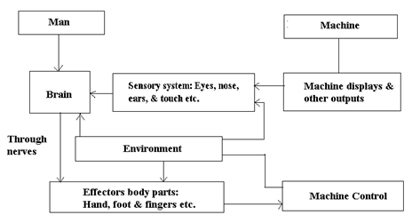
Fig. 22.1: Man –machine interface and decisions
For design of workplace for a tractor operator, following important factors/parameters should be kept in view:
1. Safety, comfort and convenience of the operator.
2. Location and construction of the operator’s work place.
3. The work place should be located on the machine so that visibility in the driving position is good without requiring the operator to work in an awkward, tiring position.
4. The operator should be able to change his working position easily.
5. Levers, pedals and instruments should be conveniently and logically located.
6. The work place should fit both tall and short operators.
7. The work area should be free of sharp edges and obstruction such as transmission cases.
3. Design of instrument panel of tractor
Good visibility for the tractor operator is more important than abundant displayed information about the tractor. In order to have proper visibility over the various displays, the instrument panel of tractor should be close to the operator’s line of vision with minimum eye movement away from the tasks. This would require prime instrument panel that would enhance operator’s performance and minimize errors. The instruments and panel controls should be logically positioned on the tractor so that all operators become familiar with the system and be able to drive the tractor with confidence. For instrument panel design main guidelines to be followed are:
-
The instrument panel designed should be symmetrical as far as possible.
-
A central zone of high priority instruments panel should be in 30° cone for easy eye movements which is 380 mm wide at 700 mm from the operator’s eye movements which is 380 mm wide at 700 mm from the operator’s eye.
-
Similar functions instruments or controls should be grouped on the panel.
-
The size of related group of instruments should be same.
-
The gauges should be grouped in the priority zone horizontally and according to their functions e.g. engine gauges to the left, steering column, or tachometer or group of indicator lights at the panel center and other functional gauges to the right side.
-
All other remaining instruments can be placed on either side of the priority group and keep their relative position same.
-
The placement of controls on the instrument panel of tractor should also follow standards. The priority controls should be on the right hand side and located such that they may not interfere with the steering wheel.
-
The horn button should always be placed to the left of key ignition switch so that it can be found out easily in an emergency by the operator.
4. Operator exposure to environmental factors
Agricultural tractors are generally used under varying agro-climatic conditions. The tractor operators are exposed directly to thermal stresses due to excessive environmental temperatures, humidity, wind, dust and even chemicals during spraying and dusting operations. These environmental parameters especially temperature, humidity, air flow and dust concentrations have considerable bearings on performance and safety of tractor operator. Most of the parameters are interrelated and the tractor operator needs to be provided with a comfortable environment in order to enhance his work efficiency and safety. These parameters must be considered for design of operators enclosure of tractor to minimize their effect and provide thermal comfort and quality air in enclosures. The comfort and bearable zones of temperature, humidity and air ventilation rates are reported in Table 22.1. However, the effect of ultraviolet radiations on humans is not known so far.
TABLE: 22.1. Comfort and bearable zones of different environmental parameters
|
Sr. No. |
Environmental Zone |
Environmental Parameters |
||
|
Temperature (°C) |
Humidity (%) |
Ventilation rate (m3/min) |
||
|
I |
Comfort Zone Lower Limit Upper Limit |
18 24 |
30 70 |
0.37 0.57 |
|
II |
Bearable Zone Lower Limit Upper Limit |
-1 38 |
10 90 |
0.14 1.4 |
i. Dust exposure: During performance of field operations with tractor a lot of dust is generated near the tractor operator’s breathing zone especially during land levelling, tillage, harvesting (combining operation) and crop threshing. However, no specific information about the dust concentration levels near operator’s breathing area is available but, some of the dust concentrations reported in field operations are:
- In tillage operations peak dust concentrations of 577 mg/m3 with mean value of 144 mg/m3 have been reported
- Permissible guideline limit for dust concentration on combines in Netherlands is 15 mg/m3.
- In tractor’s pressurized cab at 50 Pa fitted with air filters of fine quality, dust concentration of 24.7 mg/m3 in operator’s breathing zone has been found.
ii. Exposure to chemicals: Greater use of pesticides in the field crops exposes the tractor operator to hazardous chemicals during plant protection operations. Therefore, in pesticide application operations the tractor operator should either use personal protective equipments or tractor cab/enclosure as a protective device.
iii. Thermal comfort: It is defined as state of mind that expresses satisfaction with the thermal environment. Thermo-dynamic heat exchange process between tractor operator and his environment was given by Gagge et. al(1941) as given below:
S = M – E ± R ± C – W ... (22.1)
Where, S= amount of heat gained or lost, if body is in thermal balance, S=0
If S has positive value, it will cause the mean body temperature to rise and negative value will cause it to fall.
M= metabolism, 70-140 watts/m2
E= Evapo-transpiration
R= Radiation
C= Convection
W= work accomplished
The above heat exchange is related with the operator’s body surface area. The metabolic rate for a tractor operator will be in the range of 70-140 watts/m2. Average body surface area of a man will be 2m2 resulting in 140-348 watts. In order to maintain thermal equilibrium tractor enclosure environment must be maintained to balance the metabolism of tractor operator.
a. Metabolic heat of operator
Amount of heat produced in the body by metabolism depending on activity being performed by the operator is expressed by the following metabolic energy equation:
I= W+ M+ S ... (22.2)
Where, I= energy input via nutrition
W= external work done by the operator
M= metabolic heat generated in the body of operator
S= energy stored in the body
or I-W= Constant = M+S ...(22.3)
The system is in balance if all the metabolic energy M is dissipated to environment without change in quality S. The metabolic energy required to perform different physical activities is given in Table 22.2
Table 22.2: Metabolic energy required to perform different physical activities
|
Activity |
Heat produced |
|
|
(Kcal/min) |
(KJ/min) |
|
|
Basal condition |
1 |
4.3 |
|
Light physical work |
<3.50 |
<13.0 |
|
Moderately heavy physical work |
3.50-5.25 |
13.0-22.0 |
|
Heavy physical work |
>5.25 |
22.0 |
b. Heat exchange between operator body and environment
Heat from the tractor operator body is exchanged with the environment through Radiation (R), Convection (C) and Evaporation (E) as given below:
M ± R – E = ± S ... (22.4)
Where, M= heat metabolism (according to level of physical activity)
R= radiation heat gain or loss
E= evaporation heat loss
S= amount of heat gain or loss by tissues of body (In case of thermal equilibrium S=0)
c. Heat exchange through Radiation
Radiant heat gain or loss by the tractor operator is given by
R= 5.7 (ts-tr) ... (22.5)
Where, R= radiant loss or gain, kcal/m2/hr
ts= skin temperature, °C
tr= radiant temperature of surface, °C
Heat exchange through Convection
The heat gain or loss by the operator through convection is given by
![]() ... (22.6)
... (22.6)
Where,
C = amount of heat loss/gain in kcal/m2/hr
V = air speed, m/min
= skin temperature, °C
= air temperature, °C
d. Thermal comfort in operator enclosures
Tractor enclosure design: The tractor operator’s enclosure must provide clean air and proper air velocity, temperature and humidity for his thermal comfort to enhance his work efficiency and safety. Therefore, the enclosure design must include cab pressurization, filtration, air filtration, air movement, heating, cooling and window defrosting etc.
Comfort Equation: To predict comfortable environment in terms of combination of air temperature, man radiant temperature, air humidity and relative velocity, Fanger (1972) developed following comfort equation:
![]() ... (22.7)
... (22.7)
Where,
H/ADu = internal heat production per unit body surface area (ADU= DuBois area)
A tractor operator will expend 150 kcal/h.m2
Secondary person will average 50 kcal/h.m2
Icl = thermal resistance of clothing
Heavy clothing values of 0.5, 1.0, 1.5 respectively.
ta = air temperature. °C
tmrt = mean radiant temperature,°C
On bright sunny day tmrt can be 5°C to 10°C above cab air temperature
Pa = pressure of water vapour in ambient air
V = relative air velocity, m/s. Cab air velocity should be in the range of 1 to 3 m/s
Above comfort equation developed by Fanger can be effectively used to predict the effects of any combination of environmental factors on the comfortable environment for a clothed tractor operator performing field operations especially during summer season.
e. Effective Temperature Scale (ET): Effective temperature is based on simple model of human physiological response and is defined as an empirical index for human thermal comfort. Most individual will be comfortable if ET (Effective Temperature) is between 24°C and 27°C. The operator can make appropriate adjustments to meet his comfort by changing following environmental factors:
Air speed and its direction
Air temperature
Clothing worn
5. Spatial, visual and control requirement of the operator
i. Work place layout: The layout of workplace should be compatible with not only system performance requirement but also with the user. It should also ensure safety and comfort of operator and controls must be within the reach to minimize errors. Proper workplace layout requires consideration of workplace dimensions, controls and operations being controlled with due regard to:
The operator’s size
His position and the directions in which he can most easily work.
The optimum spaces in which he can manipulate the controls
Arrangement of controls and displays
Visual requirement for maximum operator efficiency
Working posture of the operator viz. Sitting, standing or squatting
Special influence such as protective clothing.
To decide about proper workplace layout following important factors must be considered:
Anthropometric parameters of operators
Placement of operator on tractor for optimum work task vision or vision of displays
Placements of controls in optimum areas for the operators.
ii. Anthropometric Data: Human being must not only fit spatially in a man task system, but must also be able to move in the work space. With the aid of anthropometric data we can provide an optimum work space layout, including good posture, contributing to considerable decrease in work load and an improvement in the performance. In design of work space and other facilities various considerations need to be taken. In particular, the type of people and their body dimensions are given in Table 22.3. Normally, during collection of human engineering data skip the first and last five percentile. Thus while designing a seat, it should be designed to accommodate a reasonable range of individuals, usually from 5th to 95th percentiles. The seat must be adjustable in a fast, easy and safe way-in horizontal and vertical direction to realize an adoption to the measurements of various population groups. Seat should be designed to take maximum weight expected. In order to realize a good performance, it is necessary that the movements of the body members are in synchrony, simple and logical motions are made, which can be performed almost automatically by the central nervous system. Lower percentile values of seat height and seat depth should be taken. Layout studies can be carried out to find maximum and optimum work space area.
Table 22.3: Body dimensions of tractor operators
|
S. N. |
Dimensions |
Percentile |
||
|
5th |
50th |
95th |
||
|
1 |
Height, cm |
162 |
173 |
185 |
|
2 |
Seating height erect, cm |
84 |
91 |
97 |
|
3 |
Seating height normal, cm |
80 |
87 |
93 |
|
4 |
Knee height, cm |
49 |
54 |
59 |
|
5 |
Popliteal height, cm |
39 |
44 |
49 |
|
6 |
Elbow rest height, cm |
19 |
24 |
30 |
|
7 |
Thigh clearance height, cm |
11 |
15 |
18 |
|
8 |
Buttock knee height, cm |
54 |
59 |
64 |
|
9 |
Buttock Popliteal length, cm |
44 |
50 |
55 |
|
10 |
Elbow to elbow breadth, cm |
35 |
42 |
51 |
|
11 |
Seat breadth, cm |
31 |
36 |
40 |
|
12 |
Weight, Kg |
58 |
75 |
98 |
iii. Placement of operator for optimum vision
The seat of tractor must give the operator an optimum field of vision and be in a position on the tractor which helps give him comfortable and safe operating conditions. Tractor operator may require vision to front and rear, or front and sides. A wide field of vision is required for both short and long ranges. Moreover close range vision is required during handling of mounted implements. These visibility requirements are satisfied by upright seating posture in order to permit easy movements of head and upper body from the front, to side, or rear as required for gathering necessary visual information. Good visibility for the operator is more important than excessive number of displays, especially when the machine is operating satisfactorily. The display area has to be close to the operator’s line of vision which requires only minimum eye movements away from his task. Table 22.4 would be quite helpful in designing the location of displays of tractor in relation to the operator.
Table 22.4: Optimum vision of operators
|
Type of movement |
Direction |
Lateral |
Direction |
Vertical |
|
Opt. Max. |
Opt. Max. |
|||
|
Head rotation only |
Left and right |
0 60 |
Up and down |
0 50 |
|
Eye rotation only |
-do- |
15 35 |
-do- |
0 25 30 35 |
|
Head and eye rotation |
-do- |
15 95 |
-do- |
0 75 30 85 |
iv. Control requirements of operator
A control is a device or hardware that can be considered as a link between the tractor and operator which converts the output of operator into input and change of state of tractor. Concept of optimum dimensions and limiting dimensions is used in placement of controls in space and dimensions usually chosen to define boundaries of the space is estimated to cater for 5th to 95th percentiles of operators. The optimum dimensions defines that most desirable space or ideal area for the location of most important and frequently used controls both in neutral position as well as in working position in any direction. The limiting dimensions define the acceptable but not the most desirable space for location of controls as the controls are neither too close nor too far from the operator. Generally two types of controls are used in tractors i.e. hand controls and foot controls.
a. Hand Controls:
Variety of hand controls is commensurate with the versatility of the hands. Hand controls can be operated either in sitting position or standing position, but seated position is preferred to the standing position especially when the controls are used for any length of time. Use of controls in standing position is less efficient and results in fatigue. Moreover, the accuracy of movement will be lesser in standing position. Hand controls are precise and have high speed. Certain hand controls can be used effectively without vision or without looking at the control e.g. gear levers. Hand controls are much more accurate and are preferred to foot control where, accuracy of control positioning is important and continuous or prolonged application of moderate or large forces (89N or more) is necessary.
b. Location of Hand controls:
The comfort zones are easy to reach and the controls which do not require movement of upper body should be located based on anthropometric dimensions of tractor operators. The comfort angles of hands should be maintained for easy reach of controls. The forearm should not be raised much above the horizontal to avoid fatigue. The controls must look efficient, attractive and easy to use. When all controls in a tractor are put together, it is desirable that these are logically arranged in orderly manner and well balanced and well placed that enables the operator to perceive the interrelationship. Preferred hand should be used where speed, accuracy or strength of controls movement is important. The optimum area of hand controls for adult operators in seated position is given in Fig.22.2.
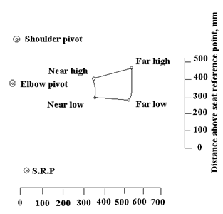
Fig. 22.2: Optimum area of hand controls for an adult operators in seated position
For proper location of hand control following points must be keep in mind.
Normally the dimensions of control placement are with respect to seat reference point.
The reference point should be adjustable at least 75 mm horizontally and 125 mm vertically.
Recommended dimensions for optimum manual control area is about 600 mm wide and 300mm to either side of midline.
When all controls cannot be placed with in the optimum area, locations immediately adjacent to optimum control areas are more desirable than those farther away.
The upper arm should make 50° angles with the upper body line and the fore arm should be 165° to the upper arm.
The controls must be kept approximately in a line ahead of shoulder joint so that the elbow is not required to move sideways from the body at angle more than 20°.
Grouping of the controls is important. Primary controls which are used continuously for a longer period of time should be placed as near to or within the horizontal planes 0-300 mm.
The controls such as engine and transmission (throttle, gear shift), hydraulic function controls which require accurate manipulation should be grouped and placed on the right hand side of operator.
The controls which generally do not require accurate adjustment i.e. P.T.O clutch, differential lock, parking brake can be provided towards left hand side of operator. However, these must be visible and reached easily by the operator. Steering wheel can be operated by left hand during use of other controls.
A difference in shape in knobs of different controls will help avoid errors in their use separately. Moreover clearance between the adjacent knobs should be 25-50 mm. if these controls are used blindly their spacing should be 125-175 mm with shape coded knobs
v. Foot Controls: Foot controls should be designed to be operated in seated position and backrest should be provided. Most people prefer the right leg especially for critical tasks. A maximum of 4 foot controls can be operated by an operator who does not require skill or practice. These are best for provision of powerful or continuous force. Foot controls are to be used in preference to hand controls where,
a) There is continuous control task and precision control positioning is not important.
b) Application of moderate to large forces (89-130N) is needed intermittently or continuously.
c) Hands are in danger of being overburdened with control tasks.
Pedals are provided in relation to floor and seat, based on anthropometric data of operators. The pedals should be provided with non-slip surface. The force required to operate each control is dependent on mechanical equipment and comfort of riding the tractor. The restoring force of pedal should be large enough to support the weight of foot. The pedals are divided into two groups:
-
Group-I: When the force used by the leg is above 44-89N, e.g. brake pedals.
-
Group-II: Where small force (about 44N) is largely obtained from the ankle for continuous operation e.g. accelerator pedal.
Location of foot controls: After determination of optimum seat position on the tractor, location of most frequently used controls in relation to seat should be provided for comfort and safety of operator. The size, shape and location of foot controls and the space in which the operator has to work must be decided based on anthropometric dimensions of operators from 5th percentile to 95th percentile. Both small and large operators sit with their heels on the same heel point. The optimum foot pedal area may be selected by locating the comforts zones which are easy to reach. The optimum foot pedal area for location of foot controls both in neutral position and when displaced in any direction. The angle of comfort of leg 20° either side of centre may be taken for location of foot controls and accordingly brake pedal and clutch pedals may be positioned.
(a) For light pedal pressures (44-89N), the foot should be applied to the pedal so that long axis of the tibia (lower leg) is immediately over and in line with the axis of pivot of pedal.
(b) The long axis of foot and lower leg should form 90o angle, thus requiring least muscular effort to hold the foot in position.
For location of foot controls in seated position in optimum areas, following are three main considerations:
(i)The fore and aft location : The distance from seat reference point (S.R.P) to pedal is an important determinant of amount of pressure exertible on the foot control, as smaller the distance more the exertaible force.
(ii)Vertical location: Where comfort matters more than the exertible force, the foot pedals can be placed below S.R.P. by vertical distances varying from type of task performed.
(iii) Lateral fore and aft location : As pedals are moved laterally from midline of leg, the exertible force decreases and discomfort of operator increases. The reduction in exertible force is related with the lateral distance and is given in Table 22.5.
TABLE 22.5: Relation between lateral distance of leg and exertible force
|
S.N.
|
Lateral distance on either Side of leg, mm |
Reduction in exertible force (%) |
|
1. 2. 3. |
75 175 250 |
10.0 27.0 37.0 |
Therefore, when placement of pedal at leg mid line is not possible, it should be displaced only 75-125 mm from mid line.
6. Operator seat
Tractor seat is most closely linked with the operator’s comfort and it must be able to provide with comfortable and controlled seated posture to the operator. It must provide the operator adequate vision to perform all the tasks safely and efficiently. All the hand and foot controls should be positioned in relation to seat in such a way that these can be operated with ease and with minimum possible efforts by the operator in seated position. Above all it should be able to reduce/absorb the mechanical shocks and vibrations transmitted to the operator. It should be strong, stable and reliable and extremely durable with minimum cost. Seat should be designed to accommodate, equally well, the total population of tractor operators, regardless of age and gender with a reasonable range of individuals, usually from 5 to 95 percentiles. The top view of tractor operator seat and the terminology related with tractor seat is given in Figs. 22.3 and 22.4 respectively. Therefore, for ergonomic design of tractor seat following important points must be considered:

Fig. 22.3: top view of tractor operator seat

Fig. 22.4: terminology related with tractor seat
i. Seat height range:
The seat height should accommodate 5 to 95% population. So, based on anthropometric data, the seat height for small people with a 10 cm seat adjustable to accommodate larger people should be selected.
Seat adjustments should provide at least 150mm of fore and aft movement for accommodating larger size operators.
Seat adjustments should provide at least 100 mm of vertical movement to accommodate larger size operators.
ii. Seat width: The seat width should be selected for 95% population.
iii. Seat depth: Again, it should accommodate 95% population.
iv. Seat cushion:
Weight of buttocks and thighs should be properly supported by a seat cushion. Human buttocks have bony structure known as ischial tuberosities are capable of transmitting body weight directly and uniformly from spinal column to the seat cushion. If seat cushion is not properly designed according to physiology of buttock region, after a prolonged time (2 to 4 hours) it may result in high degree of discomfort or pain to the operators.
Most of body weight of operator should be supported by ischial tuberosities. Peak pressure under the ischial tuberosities should be limited to 90 g/cm2 by providing flat and firm cushion in the central region of seat.
The pressure in the thighs of operator should be limited to 30 g/cm2 to avoid pinching of nerves of thighs which can be accomplished by cushion contour, cushion tilt, cushion firmness at the front and seat height above the foot support.
The seat cushion should be elevated by 5 degree seat angle from horizontal from the front side of seat.
v. Back cushion:
In order to minimize backache and fatigue the upper body of operator should be properly supported by cushion known as lumbar support according to natural geometrical shape of spinal column for the required operating posture.
The included angle between the thigh and spine or angle between back rest and seat should be at least 95°.
Backrest must support the lumbar back properly for longer period of sitting. The lumbar support should be adjustable to fit particular operating conditions.
The back cushion/support up to sacral level (75 to 150 mm above seat cushion in compressed position) should provide firm support to the operator’s back during normal operation i.e. reaction forces due to foot pedal operations.
For free swing of shoulders and arms the back cushion width of tractor seat should be limited to 330 mm.
For free swing of shoulders and arms the back cushion height of tractor seat should be limited to 330 mm.
vi. Arm rests:
(a) Armrests should be provided for support and comfort to shoulders
(b) Armrests should be adjustable vertically for varying sizes of persons.
vii. Location of controls in relation to seat:
All the hand and foot controls should be positioned in relation to seat in such a way that these can be operated with ease and with minimum possible efforts by the operator in seated position.
Leg to thigh angle should be 110-120° for pedal operation with a minimum foot-to-leg angle of 90°.

Fig. 22.5 Optimum design of tractor seat
Based on anthropometric data of tractor operators the optimum design of seat incorporating all the desirable features are reported in Table 22.6 and Fig. 22.5 given below:
Table 22.6: Optimum tractor seat design dimensions, mm
|
Sr. No. |
Description |
Item |
Maximum |
Minimum |
Nominal |
|
1 |
S.R.P height |
A |
- |
375 |
400 |
|
2 |
Seat depth |
B |
400 |
375 |
- |
|
3 |
Distance of arm length from seat back |
C |
150 |
125 |
- |
|
4 |
Distance of S.R.P from lower end back |
D |
200 |
175 |
- |
|
5 |
Back cushion length |
E |
150 |
125 |
- |
|
6 |
Fore and aft. Adjustment |
F |
150 |
100 |
- |
|
7 |
Vertical adjustment |
G |
|
|
|
|
8 |
Seat cushion width |
H |
- |
- |
475 |
|
9 |
Back cushion width |
I |
325 |
- |
- |
|
10 |
Arm rest height |
J |
250 |
200 |
- |
|
11 |
Arm rest lateral spacing |
K |
- |
- |
475 |
|
12 |
Seat cushion angle |
Ɵs |
7° |
5° |
- |
|
13 |
Back cushion angle |
Ɵb |
115° |
110° |
- |
Last modified: Monday, 7 April 2014, 8:36 AM