Site pages
Current course
Participants
General
Module 1
Module 2.
Module 3.
Module 4
LESSON 8. Fuel injection pumps–time setting, pressure adjustment (nozzle opening)
Fuel injection pump is heart of engine, it supplies fuels to the cylinders at desired pressure and time. Timing and pressure at which fuel is supplied to various cylinders is very important. Majority of the tractors and diesel engines are equipped with in-line fuel injection pumps. Time setting of one of such fuel injection pump is described as follows.
Accurate fuel injection timing is set by fuel-cut-off method using swan neck pipe on number 1 delivery valve holder after removing the delivery valve spring and peg.
1. Remove the timing gear inspection cover and the timing pin from the flywheel housing.
2. Rotate the engine clockwise and observe the ‘O’ mark on the fuel injection pump gear teeth. When the ‘O’ mark on pump gear and intermediate gear teeth are about little away from meshing, insert the longer end of the timing pin in the flywheel housing as shown in Fig: 1.
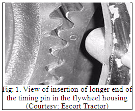
Now slowly rotate the engine clockwise to the point where the timing pin goes fully into the first hole in the flywheel and slides easily.
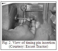
After removing the inspection cover, pull the fuel shut off rod to the point where the control rod quadrant is visible and slightly forward of the middle position. Temporarily fix fuel shut off rod in this position and proceed with fuel injection timing as shown in Fig: 2.
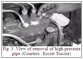
3. Remove the 1st cylinder high-pressure pipe and the delivery valve holder after loosening the holder clamp. Remove the delivery valve spring, peg, and refit the delivery valve holder. Fit the swan neck pipes shown in Fig: 3.
4. Insert a piece of cloth in the timing inspection hole towards the intermediate gear to protect against any part or tool falling in the timing housing accidentally. Loosen the three-pump gear mounting bolts.
5. Rotate the pump shaft hub clockwise as shown in Fig: 4.

6. Keep operating the hand-priming pump. A stream of diesel will flow through the swan neck pipe.
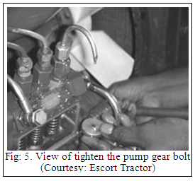
A point will come when the diesel stream will reduce to drops. Carefully turn the pump shaft hub further clockwise till the point where drops fall at an interval of about 15 seconds.Holding the pump hub at this position, tighten the pump gear mounting bolts securely. Check, the zero on the gear of F I pump aligning with the cut of the hub as shown in Fig: 5.
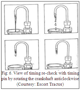
7. Recheck timing by first taking out the timing pin and then turning the crankshaft anticlockwise.Drops will appear from swan neck pipe.
Now turn the shaft clockwise till the drops reduce again to a drop every 15 seconds. Insert the pin in the flywheel hole to ascertain the correct timing to ascertain as shown in Fig: 6.
8. Complete the job and refit the Fuel Injection Pump Gear cover.
Fuel Injection Timing of Rotary Pump (DELPHI-TVS ROTARY PUMP)
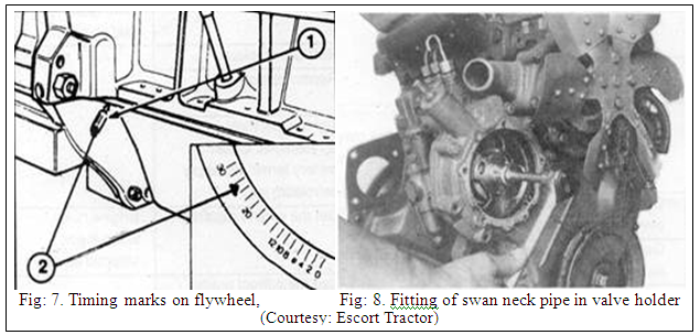
Fuel injection timing setting of rotary pump can be done by following procedure (Fig: 7.& 8.). Observe timing mark on flywheel (Fig: 7.) and fit the same neck pipe on Ist delivery valve holder (Fig: 8.)
a) The pump is supplied, with drive shaft timed and locked at start of injection position.
NOTE:
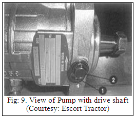
i) At this position the key on the pump drive shaft will be at 7 O’clock position viewing from pump drive end side as shown in Fig: 9.
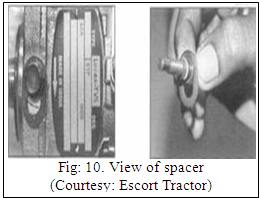
ii) At the above condition the spacer (1) provided below lock shaft screw (2) will be moving freely.
The position of the spacer is as shown in Fig: 10.
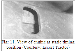
b) The engine is set to static timing position on flywheel (compression stroke on number 1 cylinder) as shown in Fig: 11.
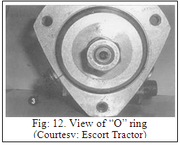
c) Ensure “O” ring (3) properly seated on the pump flange as shown in Fig: 12.
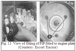
d) Fit FIP to engine plate and tighten the pump with 3 bolts (4) evenly to the specified torque to 27 Nm as shown in Fig: 13.
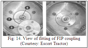
e) Fit FIP coupling (5) on to the pump drive shaft (6) [Match FIP coupling key way with FIP drive shaft key (7)] as shown in Fig: 14.
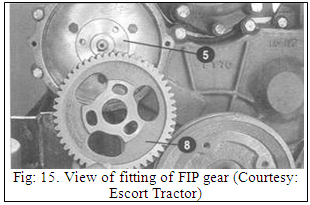
f) Fit FIP gear (8) on to the FIP coupling (5) as shown in Fig: 15.
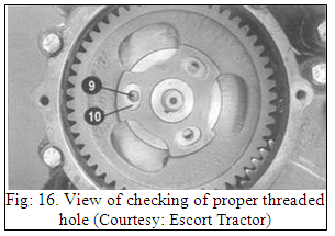
NOTE:
While positioning the FIP gear, ensure threaded holes (9) on FIP coupling is at centre of slots (10) on FIP gear as shown in Fig: 16.
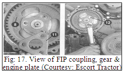
g) Fit FIP plate (11) over the FIP gear (8) and secure the FIP coupling, gear & plate with three bolts (12) and tighten the bolt to 27Nm torque as shown in Fig: 17.
h) Unlock the lock shaft timing screw (2) and position to “run condition”. Refer Fig: 18.
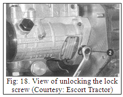
NOTE:
• At “run condition” tighten the lock shaft timing screw (2) to the recommended value of 12Nm torque.
• At the above condition, the movement of spacer (1) provided below lock shaft will be arrested.
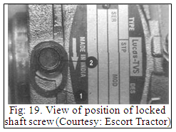
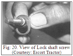
(2) The position of the locked shaft screw is as shown in Fig: 19. & Fig: 20.
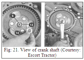
i) Place the spring washer (13) on to the pump drive shaft (6) and tighten the drive shaft nut (14) to 80Nm torque.
j) Rotate the crank shaft and ensure free rotation of gear as shown in Fig: 21.
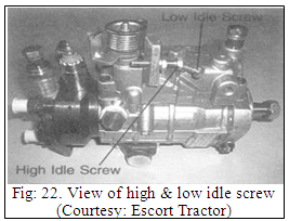
Low Idle and High Idle Speed Setting
General Precautions
a) Ensure setting the speed, only on a warmed up engine.
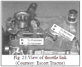
b) Slacken the throttle link before setting the speed. (Fig: 22. &Fig: 23.)
Low idle speed setting:
a) Slacken the low idle screw locknut and turn the low idle screw to set low idle speed as specified.
b) Tighten the locknut after setting the speed.
c) Recheck the low idle speed after tightening the locknut.
High idle speed setting:
a) Slacken the high screw locknut and press the accelerator pedal fully down to set high idle speed as specified.
b) Tighten locknut after setting the speed.
c) Recheck the high speed after tightening the locknut.
References:
Sharma D N. & S. Mukesh (2004). Design of Agricultural Tractor (Principles and Problems) Book Pub. Jain Brothers, New Delhi
Wadhwa D.S., Dhingra H. S. & Santokh, Singh Field operation and maintenance of tractor and farm machinery (FMP-301), laboratory manual by, Department of Farm Machinery and Power Engineering, PAU Ludhiana
Service and Maintenance Manual of Tractor by Escort Ltd. Faridabad
Last modified: Monday, 17 February 2014, 10:32 AM