Site pages
Current course
Participants
General
Module 1
Module 2.
Module 3.
Module 4
LESSON 9. Maintenance of electrical system of tractor Electrical System (including starting motor, alternator and battery)
1. The Electric Power Generation and Storage System
The electric power generation system is driven by V-belt, which gets drive from the crankshaft. It converts mechanical energy obtained from engine into electrical energy. Its main function is to recharge the battery. It also supplies electric current to the other accessories when engine is running. Generators can be DC (dynamos) or AC (alternators). Alternators can give current output up to 35 amps whereas dynamo output is limited to 12-14 amps.
Regulator is also fitted on the tractor to regulate the current produced by the generator. If no regulator is provided, the current produced by the Alternator would be so much that it would damage the battery and the other electrical units of the Tractor. High electric current is permitted to flow by the regulator when battery is in a discharged condition or when the tractor electric unit is turned on. It helps in controlling the voltage produced by the Alternator when the battery is in a charged condition or when the electric units are switched off.
The battery stores energy in chemical form. The reaction in the battery starts as soon as any circuit is completed by the action of a switch. It supplies current up to 400 amps, required to crank the engine and a limited current to the accessories. It is continually charged by the Alternator when engine is running.
In every modern tractor an electric power unit is installed to produce and store electric energy that is delivered either at low voltage or in the form of high voltages. Electrical equipment fitted on tractors is required to operate without failure for very long periods with little attention.
The power unit also provides an electrical means of cranking the engine, since the same is not capable of starting by itself. It automatically controls the voltage in the system. It also supplies power for lights and other accessories. The tractor electric system is quite simple in spite of the fact that it plays an important and multifarious role in the operation of the tractor.
The electrical system may be classified under the following headings.
-
The Electric Power generation and storage system
-
The starting system
-
The lighting system
The heart of the electrical system is the battery, it supplies current to the starting system, lighting system etc. The Alternator/dynamo keeps the battery charged.
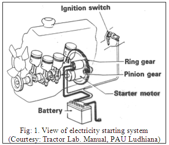
2. The Starting System
The starter is a DC motor gets a heavy dose of current from the battery. It is designed for intermittent service under heavy overload. The four poles are series connected and give high starting torque. When the circuit is completed by the solenoid switch, the pinion of the motor automatically meshes with the crankshaft ring gear. The reduction ratio between these two is 8:1 or 16:1. As the engine is started the pinion is thrown back to its initial position due to inertia effect. (Fig: 1.)
3. The Lighting System
In the lighting system of tractor the lamps (bulbs) are used for warming purpose and lights for illumination purpose. The main lamps include the headlamps, the tail lamp, the number plate lamp, the tail lamps the direction indicator lamps and dashboard lamps. . The complete lighting circuit consists of a number of individual circuits for a single lamp or a pair of lamps each with its own switch, live connection and earth connection.
The accessories like horn are connected parallel across the battery terminals. It has a separate switch. The dashboard gauges like oil pressure gauge, the temperature gauge do not have separate switch. These can be operated as soon as ignition switch is on.
Battery
The main purpose of the battery is to provide the electrical for operating the starting motor self starter. It also supplies the energy to operate the lamps and the other items of electrical equipment, some of which may be required when the engine is not running.
The battery is an electro-chemical device. In the tractor battery employ “lead” and “sulphuric acid” as the active materials, and are known as “lead acid” batteries. Each battery consists of a number of cells. As the voltage of each cell, when fully charged, is slightly more than 2 volts, 6 cells are required for a 12 volt battery.
The battery is a means of storing electrical energy in a chemical form. While the tractor is running normally the battery is automatically charged by means of the its charging system. Electrical energy is converted into chemical energy while the plates of the battery are being charged. When the battery is being discharged, the energy stored in the chemicals is released as electricity. A battery is said to be “discharged” when it is no longer capable of releasing electricity at a usable voltage. The tractor is provided with 12 Volt-80 AH / 88 AH maintenance free batteries. The negative terminal is earthed. The battery is connected in series. (Fig: 2.)
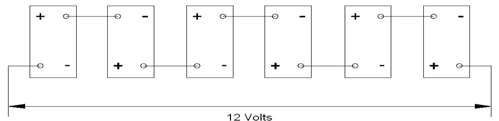
Fig: 2. View of batteries terminals connected in series (Courtesy: Escort Tractor)
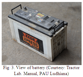
The battery (Fig: 3.) has following three major functions to perform:
a) To provide a source of current for engine starting, lighting and use of horn.
b) To help control the voltage in the electrical system.
c) To store the current produced by dynamo/alternator and to furnish the current when the electrical demands momentarily exceed the dynamo/alternator output.
a) Construction of battery
The battery is constructed in such a manner that each cell contains positive and negative plates alternately placed next to each other (Fig: 3.). Each negative plate is separated from the positive plate by a non-conducting porous separator, which prevents the plates from touching each other. All the positive plates are joined together to a post strap, forming a positive (+ve) group, and all the negative plates are joined together to a similar post strap, forming a negative (-ve) group. There is always one less positive plate than negative plates in each cell. The terminals are built up through the covers from the negative and positive group plate straps. Each cell has an opening at the top through which liquid electrolyte can be added when the filter caps are unscrewed.
b) Specific Gravity of Electrolyte of Battery
The electrolyte in a fully charged battery is 1.220 to 1.250 times as heavy as pure water when both liquids are at the same temperature. Therefore, the specific gravity of electrolyte of a fully charged battery’s 1.225 to 1.250 (For room temperatures).
Table of specific gravity and its test:
|
Battery Condition |
Specific Gravity Reading At Room Temp. |
|
Fully Charged |
1.220 / 1.250 |
|
Half Charged |
1.210 |
|
Fully Discharged |
1.150 |
|
For Initially Filling of The Electrolyte |
1.300 |
1. Battery Tests:
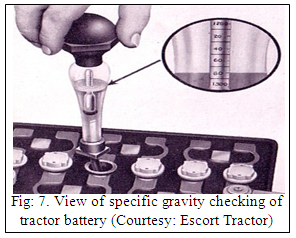
a) Specific Gravity Test:
- Check the specific gravity of a battery with a hydrometer
- With the float in a vertical position, away from the side of the barrel, take the reading with eye at the level of the bottom of the curved portion of the liquid.
- Specific gravity should not vary more than 0.025 points from cell to cell.
- If the specific gravity is below 1.250 charge the battery and inspect the charging system to determine the cause of the low battery charge. (Fig: 4.)

b) Periodical Maintenance of Battery
- Remove the battery cover. Unscrew the vent plugs and ensure that the holes in each plug are free from obstruction. If not, any dirt should be removed by means of a piece of wire. Clogged plugs will cause pressure to build up in the cells due to the production of gases during charging and may result in damage.
- Always keep the top of battery clean and dry.
- Examine the level of electrolyte in each cell, and if necessary, add distilled water to bring the electrolyte level just above the top of the separators to have the better performance and long life.
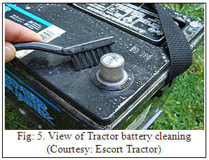
- Check battery terminal poles and if badly corroded, clean with diluted ammonia. Also examine the connections and see that the terminals clamp bolts are tight.
- Smear the battery with petroleum jelly.
- Check and ensure that the earthing lead connection from the battery is making a good clean contact with the differential housing and that the securing nut is tight.
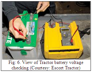
- Check the specific gravity of the electrolyte in each cell to examine the state of charge of the battery.
- Take the voltage test of each cell to cheek the condition of the cells.
- Always see that the battery is charged properly by the current produced by alternator and avoid over charging the battery. The temperature should not exceed 51.7 degree C while fast charging, otherwise it may be severely damaged.
- Under normal conditions of portion, water is the only chemical lost as a result of charging. Never add sulphuric acid to top up the battery unless the electrolyte level has been lost through spillage and electrolyte, if added must be of the correct specific gravity.
- Battery should not be left in discharged state, as this will have a bad effect upon the plates and may ruin them completely. If the battery is left out of use, see that this is fully charged every fortnightly by a short charge to prevent by tendency of the plates to deteriorate.
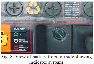
Maintenance free battery has an indicator to show the condition of the battery. Three color codes are given on the side of the indicator as follows: (Fig: 8.)
Green: O.K
White: Needs Charging
Red : Add Distilled Water
Starter Motor:
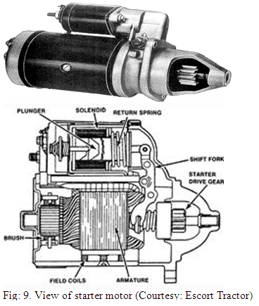
The starter motor is a four-pole series connected DC Unit. The armature shaft runs on self-lubricated bearings. Drive engagement into the ring gear is made by energizing a solenoid, which actuates a roller clutch mounted on a helical spline formed on the end of the armature shaft. Only following drive engagement with the ring gear is the electrical supply made to the starter thereby ensuring a long life for the pinion and ring gear. Over speed protection for the starter armature is given by the roller switch. (Fig: 9.)
|
Starter Motor Specifications |
|
|
Nominal Voltage |
: 12 |
|
Power Output |
: 4.2 H.P |
|
Max. HP Speed |
: 1370 R.P.M |
|
Stall Torque |
: 4.5 Kg-m |
|
Direction of Rotation |
: Clockwise |
|
Pinion |
|
|
No. of Teeth |
: 11 |
|
Module Pitch |
: 3 |
a) Checking the Starter Motor:
In the event of the starter motor failing to crank the engine at a high engine speed to allow it to start first check the state of charge of the batteries and the tightness and cleanliness of all the heavy duty electrical joints, including the engine to chassis earth lead. This usually solves most of the starting problems. If the slow speed cranking still persists or the starter motor fails to function at all, it is necessary to remove the unit from the engine. After its removal from the engine, a simple functional check can be made on the solenoid switch and the motor separately. To cheek the solenoid, connect the one lead from 12V battery to the supply terminal and the other battery lead to the body of the starter. This should cause the starter drive to move along the armature shaft. If an ammeter is put in series with the solenoid and a connection also made between the solenoid terminal and the top main terminal, than with 12V applied, the ammeter should read approximately 20 amps when the drive is fully engaged.
A high current reading (40Amps) or failure to the drive to move at all means the solenoid is faulty and should be repaired.
A direct light run check can also be made on the starter at this time. The starter motor should rotate freely at 5000-7000 rev/min and take a maximum current of 100 amps. If the motor fails to rotate, is sluggish or takes a high current, it should be thoroughly checked. During this test, the band cover around the starter yoke may be removed by loosening the single bolt fixing. Excessive sparking indicates that the commutator or the brushes may need attention. If just dirty the commutator can be cleaned with a petrol-moistened rag. Similarly the dirty or sticky brushes in the brush holder should be cleaned.
If prior to removing the starter from the engine, starter rotates but the engine does not, this indicates either sticky or faulty roller clutch drive. The subsequent solenoid check will reveal whether the drive is sticky on the shaft and a simple head cheek can be made on the drive itself. It should be possible to freewheel the drive pinion in a clockwise direction, but the whole armature should rotate when the pinion is turned anticlockwise. If the pinion rotates freely in both the directions, the drive will need to be replaced as a unit. Similarly, if the drive slips under load, replacement is also necessary; this fault is however unusual.
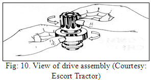
Drive Assembly Check
Hold the drive assy. and inspect the pinion to ensure that it can be rotated in the direction of Starter rotation and that it should be locked in the opposite direction rotation. (Fig: 10.)
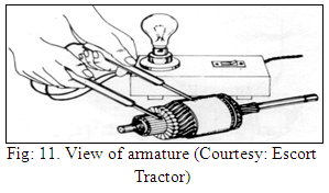
a) Armature Insulation Test
Use 110 Volts AC mains 15W bulb with two probes, connect as shown in figure. Bulb must not glow when the probes are connected between any one of the commutated segments and Armature core. If the bulb glows the fault is with the insulation. Replace the Armature. (Fig: 11.)
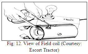
b) Field Coil Check
Make sure the insulation is proper. Use 110 Volts AC mains ISW bulb with two probes. Connect as shown in fig. Bulb must not glow when the probes are connected to the field coil terminal and to the clean surface of the yoke. Locate the fault and rectify by re-taping or replacing the field coil assembly. (Fig: 12.)
c) Solenoid Check
Before testing the-starter to locate the defective component check the solenoid completely.
To check the solenoid functions connect 12 Volts supply across the solenoid terminal and body of the solenoid. Check for complete movement of the drive. If not, engaging lever or solenoid could be defective. Locate the faulty component and replace.
Alternator:
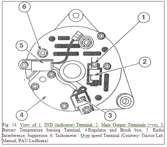
Alternator provides a higher maximum output than the equivalent direct current generator and also increased charge rates at lower engine speeds. Unlike a direct current generator, the alternator does not require a commutator and can be run safely at higher speeds. (Fig: 14.)
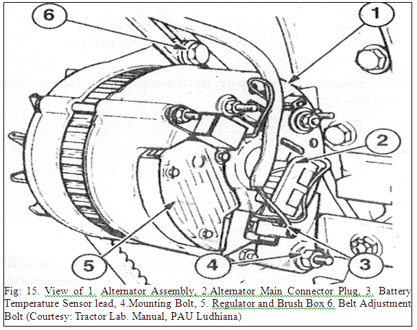
The alternator is mounted at the front of the engine being belt driven from the crankshaft pulley. (Fig: 15.)
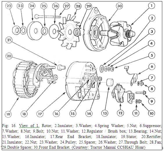
The alternator comprises principally
- Rotor
- Stator
- Rectifier Pack
- Regulator / Brush Box
a) Rotor
The rotor and brush gear provide the magnetic field of the alternator unlike a direct current generator where the field is stationary. The rotor is belt driven from the engine through a pulley keyed to the rotor shaft, which runs in heavy- duty sealed ball race bearings. An integral fan, adjacent to the pulley, draws cooling air through the alternator. Current is supplied to and returned from the rotor field coil via two carbon brushes, which bear against slip rings on the rotor shaft. As current passes through the copper wire of the rotor field coil a magnetic field is produced and contained within an armature formed into pole shoes. The configuration of the pole shoes ensures concentration of the magnetic field.
b) Stator
The stator contains the windings into which current is induced by the revolving magnetic field of the rotor. Main components of stator are shown in Fig16.
The stator is fabricated from laminations of thin steel pressings onto which three separate wires are wound. The laminations are specially formed to concentrate and collect the magnetic field. During each complete revolution of the rotor, all three stator windings have induced currents passing first in one direction and then the other; in other words a 3-phase alternating current. Because alternating current is generated in a series of pulsations, the rotor features six pairs of poles to provide an overall smoother output. For every revolution of the rotor the output characteristic of each stator winding completes six cycles.
Alternating current (AC) is unsuitable for charging the battery, which requires pure direct current (D.C.). Therefore, the three-stator windings are connected to a rectifier pack, which rectifies or converts the alternator output to direct current.
Regulator and Brushes:
The regulator controls and maintains the alternator output voltage at a safe working level. The regulated voltage level is established in manufacture and cannot be adjusted in service: The regulator components are housed in a sealed assembly, which is integral with the alternator brush box. Individual brush box and regulator components are not serviceable and have to be replaced as a complete assembly.
Alternator Operation:
When the start key switch is turned on, an amount small current flow from the battery through the rotor field windings. The circuit is made via the charge indicator warning light, alternator terminal IND, the rotor field winding, the alternator regulator and ground.
At this stage the warning light is illuminated and the rotor partially magnetized. When the engine is started and the partially magnetized rotor revolves within the stator windings a 3-phase alternating current is generated. A constant portion of the generated current is converted to direct current by the three field diodes incorporated in the rectifier pack.
This direct current is fed back to supplement the current flowing through the rotor field winding. This action results in an ever-increasing magnetic influence of the rotor along with an associated rapid rise in generated output current and voltage.
During the rise in generated output voltage (reflected at terminal IND) the brilliance of the warning light is reduced and when the voltage at the IND terminal equates to that at the battery side of the warning light the lamp is extinguished.
The voltage continues to rise until the predetermined regulated voltage level is reached.
In the event of drive belt breakage the voltage will not build up within the alternator and so the charge indicator light will remain on to indicate failure.
5. Trouble Shooting Chart
Battery
|
Symptom |
Probable Cause |
Remedy |
| Low specific gravity of electrolyte in Cells |
Battery worn out |
Replace after test confirm diagnosis. |
|
Infrequent driving. |
Charge by driving or by small bench charge periodically. |
|
|
Loose fan belt |
Tighten / replace belt |
|
|
Low open Circuit Voltage setting in Regulator. |
Set regulator correctly. |
|
|
Leakage Currents. |
Check, clean battery top. |
|
|
Short circuit in wiring. |
Replace faulty wiring |
|
|
Plates sulphated. |
Recover by sulphation treatment |
|
|
Loose terminal clamps, corrosion. |
Clean terminals clamps, Tighten clamps |
|
| Abnormal rise in temperature during charge (generally with abnormal premature gassing) |
Plates sulphated. |
Recover by sulphation. |
|
Short circuit in cells |
Repair / replace faulty cells |
|
|
High charge current |
Lower to normal value. |
|
| Abnormal color of plates: separators bleached darkened; white spots on top of plates |
Contaminated electrolyte |
Dump acid, wash inside of cells with distilled water, recharge with new electrolyte |
|
Low electrolyte levels. |
Top-up |
|
|
Sulphated plates. |
Recover by sulphation |
|
| Excessive topping required. |
Overcharging |
Check, correct regulator setting |
For electrical system of tractor
|
Symptom |
Probable Cause |
Remedy |
|
| Several or all lights do not illuminate Battery discharged. |
Battery discharged. |
Check battery and charge or renew. |
|
| Loose or defective battery cable connections. |
Inspect, clean and tighten connections |
||
| Loose harness connectors. |
Check and ensure connectors securely engaged. |
||
| Fuse (s) burnt out. |
Inspect and renew, check circuit before reconnecting power. |
||
| Faulty wiring. |
Check lighting circuit wiring and repair or renew. |
||
| Defective light switch. |
Check and renew. |
||
| Several light bulbs burnt out due to defective voltage regulation. |
Check and renew voltage regulator. |
||
| Individual lights do not illuminate Burnt out bulb. |
Burnt out bulb. |
Check and renew. |
|
| Defective or corroded bulb contacts. |
Inspect, clean or renew. |
||
| Fuse burnt out. |
Inspect and renew, check circuit before reconnecting power. |
||
| Loose or broken wires. |
Inspect, secure, repair or renew wiring. |
||
| Poor ground connection. |
Inspect, clean and tighten ground connections |
||
| Lights burn out repeatedly Loose or corroded wiring connections. |
Loose or corroded wiring connections. |
Inspect, secure, repair or renew wiring |
|
| Loose bulb or lamp mounting bracket. |
Inspect, tighten or renew. |
||
| Faulty Voltage regulator. |
Check and renew voltage regulator. |
||
| Plough lamps inoperative Side lights switch not turned on. |
Side lights switch not turned on. |
Ensure sidelights are illuminated. |
|
| See "Individual lights do not illuminate. |
See "Individual lights do not illuminate". |
||
| Flasher lamps do not illuminate Fuse blown. |
Fuse blown. |
Inspect and renew, check circuit before reconnecting power. |
|
| Flasher lamps do not illuminate Flasher unit inoperative |
Flasher unit inoperative |
Check and renew. Flasher unit may be by passed by interconnecting terminals. This enables circuit continuity to be checked. |
|
| Flasher switch inoperative. |
Check and renew. |
||
| Defective wiring or connections. |
Inspect circuit, clean and tighten connections or renew wiring. |
||
| Individual flasher lamp does not illuminate. Burnt out bulb. |
Burnt out bulb. |
Check and renew. |
|
| Corroded or loose bulb contacts. |
Inspect, clean, tighten or renew. |
||
| Poor ground connection or damaged wiring. |
Inspect, clean and tighten connection, repair or renew wiring. |
||
| Turn indicator pilot bulb (s) inoperative. Faulty bulb (s). |
Faulty bulb (s). |
Check and renew. |
|
| Defective flasher unit. |
Check and renew. |
||
| Faulty Wiring or connections. |
Inspect, clean and tighten connections or renew wiring. |
||
| Main flasher lamp bulb contacts or ground connection corroded (failing to draw full current). |
Inspect, clean, and tighten connections and ground connections. |
||
|
|
|||
|
Instrumentation |
|||
| Warning lights and gauges inoperative Faulty key start switch. |
Faulty key start switch. |
Inspect and check. |
|
| Fuse (s) burnt out. |
Inspect and renew, check circuit before reconnecting power. |
||
| Loose or broken wiring. |
Inspect circuit, tighten connections or renew wiring. |
||
|
Starting System |
|||
| Engine will not crank and starting motor relay or solenoid does not engage Battery discharged. |
Battery discharged. |
Check battery and charge or renew. |
|
| Key start switch, safety starts switch, relay or solenoid inoperative. |
Check circuit and repair or renew faulty components. |
||
| Starting circuit open or high resistance. |
Check circuit connections and repair or renew faulty wiring. |
||
| Engine will not crank but starting motor relay or solenoid engages Battery discharged. |
Battery discharged. |
Check battery and charge or renew |
|
| Defective starting motor connections or loose battery connections. |
Check, clean and tighten connection |
||
| Starting motor faulty. |
Inspect, repair or renew. |
||
| Relay or solenoid contacts burnt. |
Renew relay or solenoid. |
||
| Engine seized. |
Check engine crankshaft free to turn. |
||
| Starting motor turns but does not crank engine Defective starting motor drive assembly. |
Defective starting motor drive assembly. |
Inspect and repair or renew. |
|
| Defective solenoid or pinion engagement levers. |
Inspect and repair or renew. |
||
| Defective flywheel ring gear. |
Inspect and renew. |
||
| Engine crank slowly Discharged battery. |
Discharged battery. |
Check battery and charge renew. |
|
| Excessive resistance in starting circuit. |
Check circuit connections and repair or renew faulty wiring. |
||
| Defective starting motor. |
Inspect and repair or renew. |
||
| Tight Engine. |
Investigate cause and effect repair. |
||
|
Charging System |
|||
| Battery low in charge or discharged Loose or worn dynamo / alternator drive belt. |
Loose or worn dynamo / alternator drive belt. |
Check & adjust tension or renew. |
|
| Defective battery will not accept or hold charge. |
Check condition of battery and renew. |
||
| Electrolyte level low. |
Check, fill and charge. |
||
| Excessive resistance due to loose charging system connections. |
Check, clean and tighten circuit connections. |
||
| Defective voltage regulator. |
Check and renew. |
||
| Defective dynamo / alternator. |
See dynamo / alternator trouble shooting guide. |
||
| Alternator charging at high rate (battery consumes more electrolyte) Defective battery. |
Defective battery. |
Check condition of battery and renew. |
|
| Defective voltage regulator. |
Check and renew. |
||
| Defective alternator. |
See alternator trouble shooting guide. |
||
| No output from alternator Alternator drive belt broken. |
Alternator drive belt broken. |
Renew and tension correctly. |
|
| Loose connection or broken cable in charging system. |
Inspect system tighten connections and repair or renew faulty wiring. |
||
| Defective voltage regulator. |
Check and renew |
||
| Defective alternator. |
See alternator trouble shooting. |
||
| Intermittent or low alternator output Alternator drive belt slipping. |
Alternator drive belt slipping. |
Check and adjust tension or renew. |
|
| Loose connection or broken cable in charging system. |
Inspect system tighten connections and repair or renew faulty wiring. |
||
| Defective voltage regulator. |
Check and renew |
||
| Defective alternator. |
See alternator trouble shooting. |
||
|
ALTERNATOR |
|||
| Alternator light dims and / or battery low
|
Faulty rotor slip rings or brushes |
Inspect and repair or renew. |
|
| Faulty External charging circuit connections. |
Inspect system clean and tighten connections. |
||
| Warning light goes out-becomes brighter with increased speed Faulty rectifier or rectifying diodes. |
Faulty rectifier or rectifying diodes. |
Check and renew. |
|
| Defective voltage regulator. |
Check and renew. |
||
| Warning light normal but battery boiling Faulty battery temperature sensor (where fitted). |
Faulty battery temperature sensor (where fitted). |
Check and renew. |
|
| Defective voltage regulator. |
Check and renew. |
||
| Warning light normal but battery discharged Faulty stator. |
Faulty stator. |
Check and renew. |
|
| Faulty rectifier or rectifying diodes. |
Check and renew. |
||
| Loose or worn alternator drive belt. |
Check and adjust tension or renew. |
||
| Warning light illuminated continuously and / or flat battery Warning light extinguished continuously and / or flat battery Faulty battery temperature sensor (where fitted). |
Faulty battery temperature sensor (where fitted). |
Check and renew. |
|
| Faulty rotor, slip rings or brushes. |
Inspect, repair or renew. |
||
| Defective stator. |
Inspect and renew. |
||
| Defective rectifier or rectifying diodes. |
Check and renew. |
||
| Burnt out bulb. |
Check and renew. |
||
| Warning light extinguished continuously and / or flat battery
|
Alternator internal connections. |
Inspect & test circuitry, repair or renew. |
|
| Defective voltage regulator. |
Check and renew. |
||
| Faulty rotor, slip rings or brushes. |
Check, repair or renew. |
||
| Defective stator. |
Check and renew. |
||
| Warning light flashes intermittently
|
Alternator internal connections. |
Inspect & test circuitry, repair or renew. |
|
| Defective rotor, slip rings or brushes. |
Check, repair or renew. |
||
| Warning light dims continuously and / or flat battery |
Defective voltage regulator. |
Check and renew. |
|
For starter motor:
|
Symptom |
Probable Cause |
Remedy |
| When starter is operated its shaft fails to rotate or rotates slowly |
Discharged / Defective battery |
Recharge battery. |
|
Loose or oxidized battery terminals/ corroded or loose connectors / defective earth connectors |
Clean the terminals. Tighten all connections and smear petroleum jelly. |
|
|
Starter terminals or carbon brushes earth short circuited |
Spot faulty earthing and deal with it. |
|
|
Brushes worn out and do not have proper contact with Commutator. Dirty or oily or badly burnt commutator due to sticky brushes |
Renew brushes / clean commutator. If comm. is badly burnt due to sticky brushes skim / replace complete armature. |
|
|
Solenoid switch defective or points badly pitted. |
Replace switch / clean the contacts. |
|
|
Armature/Field coil defective. |
Replace Armature or field coil as the case may be. |
|
|
Excessive voltage drop |
Check and rectify circuit of starter. |
|
| Pinion fails to engage, though armature rotates |
Pinion fouled |
Clean it. |
|
Burr formation on pinion or ring gear |
Deburr it by filing |
|
|
Defective Auxiliary Coil |
Change Auxiliary Coil |
|
|
Mounting loose |
Tighten mounting units |
|
|
Worn CE/DE bush |
Change CE/DE bush |
|
|
CE bearing pin loose |
Check the tightness of bearing pin fixing screws and caulk if necessary |
|
| Starter continues running after release of starting switch |
Sticky starting switch |
Disconnect starter cable immediately at battery or starter. Repair / replace switch |
|
Short in wiring Harness |
Repair fault in wiring |
|
|
Dry-DE bush |
Trace cause and lubricate |
|
|
Pinion flywheel gear fouled or damaged |
Clean thoroughly/ deburring gear and pinion by filling (push the vehicle to and fro with gear engaged). |
|
| Pinion engages but starter does not crank the engine |
Insufficiently charged battery corroded terminals |
Change the battery or clean terminals |
|
Insufficient pressure on carbon brushes or worn out brushes |
Change brush springs / brushes |
|
|
Shorted / Earthing armature |
Change armature. |
|
|
Slipping Clutch Assembly |
Change clutch assembly |
|
|
Partially Earthing field coil |
Change field coil |
|
|
Solenoid contact not making |
Re-set solenoid and replace spring |
References:
Wadhwa D.S., Dhingra H. S. & Santokh, Singh Field operation and maintenance of tractor and farm machinery (FMP-301), laboratory manual by, Department of Farm Machinery and Power Engineering, PAU Ludhiana
Service and Maintenance Manual of Tractor by Escort Ltd. Faridabad
Sharma, D.N. Tractor Manual Department of Farm Power and Machinery, CCSHAU Hisar
Last modified: Monday, 17 February 2014, 11:30 AM