Site pages
Current course
Participants
General
MODULE - I
MODULE - II
MODULE - III
MODULE - IV
MODULE -V
MODULE - VI
MODULE - VII
MODULE - VIII
MODULE - IX
REFERENCES
LESSON - 34 STEAM ENGINE, NON-EXPANSIVE AND EXPANSIVE ENGINE CYCLE
34.1. STEAM ENGINES
We have already discussed that the steam engine is used in steam power plant to covert thermal energy of steam into useful mechanical work by expanding the steam. The steam engines are sometimes called external combustion engines. The first steam engine was developed by James Watt in 1763. After developing high efficiency devices like steam turbine, gas turbine, IC engines, etc, the steam engines are outdated, however, it is still being used for certain applications because of the following advantages: —
Advantages
(i) Any fuel can be burnt in it to produce steam,
(ii) Its initial cost is reliable and low,
(iii) Its construction is strong and simple,
(iv) Its efficiency is better on part load and has excellent torque characteristics,
(v) It is possible to reverse the direction of rotation,
(vi) Below 1470 kW power output, its steam economy is as good as steam turbines.
Applications
Steam engines are used for the following purposes:
(a) For driving reciprocating water pumps and compressors.
(b) For driving locomotive and hoisting where reverse operation and wide flexibility in speed control are required.
(c) For heating and process work such as in laundries, hotels, textile manufacturing, wood working mills, paper mills, chemical industries and others.
34.2. CLASSIFICATION OF STEAM ENGINES
These steam engines can be classified according to its construction and operating features. Detailed classification is as below:
(a) Axis of cylinder. Based on the position of cylinder axis, the steam engines are classified as (i) vertical (ii) horizontal, (iii) inclined steam engines.
(b) Action of steam. Based on action of steam on the piston, the engines are classified as:
(i) Single acting steam engine: steam acts on one side of the piston only while on the other side of the piston, the pressure is more or less atmospheric.
(ii) Double acting steam engine: steam is alternatively admitted on both sides of the cylinder.
(c) Number of cylinders. Based on number of cylinders the engine is:
(i) Simple steam engine: In which the total expansion of steam takes place in one cylinder.
(ii) Compound steam engine: In which the total expansion of steam takes place in more than one cylinder.
(d) Exhaust System. On the basis of steam exhaust from the engine:
(i) Condensing engine: In this the exhaust steam from steam engine passes in a condenser where steam is condensed at low pressure than the atmosphere.
(ii) Non- condensing steam engine: In this the exhaust is directly passed to the atmosphere, such as, in locomotive engine.
(e) Expansion of steam in cylinder. On the basis of steam expansion in steam engine cylinder, the engines are classified as:
(i) Non-expansive: In non-expansive engine, no expansion of steam takes place inside the cylinder e.g. direct acting pumps, in rolling mills and in winches.
(ii) Expansive engines: In an expansive engine, the expansion of steam takes place inside the cylinder.
(f) Valve gears. Based on valve gears mechanism of steam engine, the engines are classified as (i) D-type and (ii) Corliss or Poppet type.
(g) Speed. According to the running speed of the engine it can be classified as,
i) Low speed engine: Engine runs at 100 or less revolution per minute.
ii) Medium speed engine: Engine runs at 110 to 200 revolutions per minute.
iii) High speed engine: Engine runs above 200 or more revolution per minute.
(h) Use. Based on the applications of steam engine, these are classified as,
i) Locomotive or Portable Engines
ii) Stationary Engines
iii) Marine Engines
(i) Governing Methods Based on the governing method employed, the steam engine classification is made as under:
i) Throttle Governing: In this method the speed of engine is controlled by means of valve in the steam pipe which regulates the pressure of steam entering the engine.
ii) Automatic Cut-Off Governing: In this method governor controls the quantity of steam admitted to the cylinder while the pressure of entering steam remains constant.
34.3. PRINCIPAL PARTS OF A SIMPLE STEAM ENGINE.
The principal parts of a simple steam engine is shown in Fig. 34.1. Details of these parts are as follows:

Fig. 34.1. Detail of a steam engine
Cylinder. This a hollow cylinder in which the piston moves to and fro due to the action of steam. It is made of cast iron. One end of the cylinder is known as head/cover/front end, which is closed by means of separate cover, the other end is known as crank/back end, through which the piston rod passes.
Valve chamber/Steam chest. It is generally cast integral with the cylinder. It is closed by a cover termed as steam chest cover which may be circular or rectangular depending upon the shape of the valve operating in it. There are two openings known as steam ports leading from cylinder to the steam chest. These two ports, one at each end of the cylinder, are provided for flow of steam from steam chest to the cylinder or from cylinder to the steam chest. A third passage known as exhaust port is provided between the two steam ports for the discharge of steam from the cylinder to the outside.
Piston. The piston is a cylindrical piece, generally made of cast iron. The outer periphery of each piston is accurately machined to running fit in the cylinder bore and is provided with several grooves into which piston rings are fitted. The main function of piston is to convert the pressure energy of the steam into its reciprocating movement (to and fro in the cylinder) and transmits force to the cross-head through the piston rod. It is the movement of the piston which allows for the expansion of steam in the cylinder, and thus work is obtained.
Piston rings. The function of the piston rings is to prevent any leakage of steam past the piston and also prevents any wear and tear of the piston. Whatever the wear and tear that takes place, it takes place in the piston rings only which are easily replaceable. The piston rings are made of cast iron and are located in the circumferential grooves cut in the piston.
Piston rod. The piston rod connects the piston and cross head. It is generally made of mild steel.
Stuffing box. This is placed at the point where the piston rod passes through the cylinder cover and valve rod passes through the valve chamber/chest. In this way, it prevents the leakage of steam from the cylinder and valve chamber/chest to the atmosphere.
Crosshead and guide. The cross head H is a block by means of which the ends of the connecting rod N and the piston rod P are joined. Usually the end of the piston rod is forged or attached with the crosshead and one end of the connecting rod is connected with it by means of a crosshead pin or gudgeon pin (Fig. 34.2). The movement of the crosshead is controlled by means of guide bars G, so that it gets only the sliding motion. The function of the cross head is to prevent the piston rod from getting bent.

Fig. 34.2. Cross-head
Connecting rod. The connecting rod ‘N’ connects the piston and the crank ‘C’(Fig 34.2). One end of the connecting rod, called the small end, is connected to the cross head and the other end, called the big end, is connected to the crank with the crank pin. The crank is fitted on the crank shaft CS. The function of connecting rod is to transmit the reciprocating motion of the piston into rotary motion of the crank shaft. The connecting rod is usually made of forged steel.
Crank shaft. The crankshaft is the principal rotating part of the engine. It serves to convert the forces applied by the connecting rods into a rotational force. It controls the motion of the piston and must be designed to cause them to reciprocate in proper sequence. The crank shaft is supported by bearings and it is fitted with the eccentric and flywheel. The crank is usually made of forged steel. The crankshaft is usually drilled to permit oil to be circulated from entrances in the main bearing areas to the cranks pins.
The axis of crank pin is at some distance away from the axis of the crank shaft, called radius of the crank. The radius of the crank is equal to half of the stroke length. The position of crank pin with respect to crank shaft controls the position of the piston in the cylinder and causes it to reciprocate in proper sequence. Two extreme positions of the crank pin are known as dead centers. For vertical engines these are known as top dead centre position and bottom dead centre position and for horizontal engines, these are called the inner dead centre position and outer dead centre position.
Eccentric. It is made of cast iron, and is located on the crankshaft. The axis of eccentric is always at a short distance away from the axis of the crank shaft, and is called radius of the eccentric. It converts the rotary motion of the crank shaft into the reciprocating motion of the slide valve through valve rod and eccentric rod. The position of axis of eccentric with respect to crank shaft controls the position of the slide valve in the valve chamber and causes it to reciprocate in proper sequence.
The relative position of the axis of eccentric with respect to axis of crank pin provides the required valve position with respect to the position of the piston.
Valve rod and eccentric rod. The valve rod connects the valve and the eccentric rod through a valve rod guide, which prevents the bending of the valve rod, while the eccentric rod connects the valve rod and the eccentric. The eccentric rod converts the rotary motion of the eccentric into reciprocating motion which is transmitted to the valve through the valve rod. Both the rods are made of mild steel or Al-alloy or carbon steel.
Valve. The valve may be D-slide or any other type. It reciprocates over the valve seat in the steam chest. It admits or exhausts steam to or from the cylinder from or to the steam chest at the proper time through the ports.
Steam jacket: The steam from boiler is circulated through the steam jacket surrounding the cylinder to maintain the cylinder walls at high temperature. The steam jacket is cast integral with the cylinder.
Fly wheel. It is a heavy mass mounted on the crankshaft to minimize the cyclic fluctuation of speed by absorbing energy when the supply is greater than the demand and releasing energy when the supply is less than the demand. By employing a flywheel the turning moment becomes uniform at the crank-shaft.
Governor. The function of the governor is to maintain the speed of the engine fairly constant irrespective of the load. It is placed generally at the inlet of the steam pipe and is driven by a belt through the crankshaft.
Main bearings. Generally two main bearings are provided at each end of the crankshaft to support it; the bearings are attached to the frame.
34.4. CYCLE OF OPERATIONS
In a Steam engine, the cycle of operations is completed in two stroke of the piston, that is, in one revolution of the crank shaft. Generally, steam engines are of double acting type and the same operations take place on both sides of the piston.
The Non-expansive Engine Cycle and Expansive Engine Cycle operation are explained below with the help of a p-V diagram showing how the pressure and volume of steam vary in the cylinder during one revolution of the crank shaft i.e. during one complete working-cycle or engine-cycle.
43.4.1. Non-expansive Engine Cycle
In this cycle, no expansion or compression of steam takes place inside the engine cylinder. The steam exerts a constant pressure upon the piston. Here the edge of the slide valve is equal to the gap of the steam port. During the cycle, the angle between axis of eccentric and axis of crank pin is kept 90° which moves the sliding valve half stroke advance with respect to piston.
First stroke: Suppose the piston P is at the beginning of the stroke at the at the head end (extreme left hand side of the cylinder). The sliding valve is at the middle of its stroke and both the steam ports are fully closed by the slide valve V [Fig. 34.3 (a)]. Now the piston and the slide valve move away from the head. So there is a gradual opening of steam ports due to the movement of the slide valve. Steam enters at constant pressure through the steam port No. 1 and discharges at constant pressure through the steam port No. 2 [Fig. 34.3 (b)]. When the piston reaches at the middle of its stroke, the sliding valve is at the crank end (extreme right) of its stroke and both the steam ports are fully opened by the slide valve [Fig. 34.3 (c)]. When the piston starts moving toward the crank end from middle of its stroke, the slide valve reverses its direction towards left (i.e. moves away from crank end) and thus both the steam ports are gradually closing [Fig. 34.3 (d)]. When the piston reaches at the crank end of its stroke, the sliding valve is at the middle of its stroke and the steam ports are completely closed. Thus the first stroke is completed [Fig. 34.3 (e)].
Second stroke: The piston moves towards the cylinder head from the crank end. The slide valve also moves in the same direction from the middle of its stroke. Thus, again there is a gradual opening of the steam ports [Fig. 34.3 (f)]. The steam is driven out by the piston through the steam port No. 1 to the exhaust port E for its discharge and the admission of steam takes place through the steam port No 2. When the piston reaches at the middle of its stroke, the sliding valve is at the head end (extreme left) of its stroke and both the steam ports are fully opened [Fig. 34.3 (g)]. Now the slide valve reverses its direction towards right (i.e. moves away from head end) with gradual closing of the steam ports [Fig. 34.3 (h)]. When the piston reaches at the end of its stroke at the extreme left hand side (i.e. at the head end), both the steam ports are completely closed [Fig. 34.3 (a)]. Now- the cycle is completed and the same operations are repeated again.


1, 2 : Steam Port, Ex- Exhaust port, P – Piston, V – sliding valve,
Fig. 34.3. Operation of a non-expansive steam engine
P-V diagram: The operations of a non-expansive engine-cycle can be represented with the help of a pressure volume diagram shown in Fig. 34.4. Here the action of steam only on the left hand side of piston is considered.
During the first stroke, the steam port is opened either partially or fully for admission of steam and so the steam pressure remains constant during the whole of the stroke though there is a gradual increase in volume. It is represented by the horizontal line Ae.
At the end of the first stroke the steam comes out from the cylinder at constant volume with decrease in pressure. It is represented by the vertical line ‘eE’.

Fig. 34.4. p-V diagram for Non-Expansive steam engines
At the second stroke, the steam discharges from the cylinder at constant pressure as the steam port is opened fully or partially for the exhaust of steam and there is gradual decrease in volume. This operation is indicated by the horizontal line ‘Ea’.
At the end of the stroke the fresh steam enters into the cylinder at constant volume. So there is an increase in pressure inside the cylinder. It is denoted by the vertical line ‘aA’.
Thus, the cycle is completed and its p-V diagram is represented by the closed figure ‘aAeE’. The area of ‘aAeE’ represents the amount of work done by the one side of the piston per cycle.
43.4.2. Expansive Engine-cycle
In an expansive engine-cycle, the expansion and compression of steam occur in the engine cylinder. As a result more amount of work can be obtained due to the expansion of the same amount of steam than the non-expansive engine. Here the edges of the slide valve are greater than the gap of the steam port as shown in Fig. 34.5. During the cycle, the angle between axis of crank pin ‘CP’ and axis of eccentric ‘E’ is greater than 90° i.e. = (90°+ α). The amount of angle by which the eccentric is in advance of 90° is known as angle of advance or angle of lead (α).
When the slide valve is in its middle of its stroke (Fig. 34.5), then the amount by which it extends or overlaps beyond the steam port ‘SP’ is called the lap of the valve. The amount by which it overlaps the outside edge of the steam port is known as the outside lap or steam lap ‘o’ of the valve and the amount by which it overlaps the inside edge of the steam port is known as the inside lap or exhaust lap ‘i’ of the valve.

Fig. 34.5. Inside and outside Laps when sliding valve is in middle of stroke.
Considering the action of steam on the left hand side of the piston only, the operations are explained with the help of a p-V diagram (Fig. 34.7). Similar operations will be repeated on the other side of the piston.
First stroke: Suppose the piston is at head end (left hand side) of the cylinder [Fig. 34.6 (a)] and the position of sliding valve is such that a small part of the steam port is opened by the sliding valve for the admission of steam at constant pressure pa through the steam port No. 1. It is represented by point a on the p-V diagram (Fig. 34.7) called the point of admission. The amount of port opening at the point of admission is called the lead of the sliding valve ‘e’. At this position of piston, the points corresponding to crank pin ‘CP’ and eccentric ‘E’ are also shown in Fig. 34.6 (a).
Now the piston starts moving away from the cylinder head at constant pressure pa with gradual increase in volume. During this part of stroke, the No. 1 steam port remains open and steam enters the cylinder at constant pressure through port No. 1. It is represented by the horizontal line ac on p-V diagram. When piston reaches at the position shown in Fig. 34.6 (b), for the head end side the outer edge of the valve coincides with the outer edge of the steam port thus closes the No. 1 steam port and admission of steam inside the cylinder is suspended. It is represented by point c on the p-V diagram which is called the cut-off point. As piston moves further to right towards crank end for completing its first stroke Fig. 34.6 (c,d), the hyperbolic expansion of steam takes place with increase in volume and decrease in pressure. This is represented by the curve cr. At the end of stroke, when piston reaches at the crank end as shown in Fig. 34.6 (e) (represented by point r on p-V diagram), the steam port No. 1 opens again and steam is discharged from the cylinder at constant volume until its pressure is decreased to the exhaust pressure pb (represented by vertical line rd). The point r is called the point of release or blow down. The first stroke is thus completed.
Second stroke: The second/return stroke begins with a movement of piston from crank end towards the cylinder head. During this part of the stroke the steam port is open and the steam is discharged at constant pressure pb from the cylinder. This is denoted by the line dk on p-V diagram. When the piston reaches at point shown in Fig. 34.6 (f) the steam port closes thus the discharge of steam is stopped. On p-V diagram this is represented by point k called the point of compression or cushioning. Now as the piston moves further towards cylinder head (left) Fig. 34.6 (g,h), the entrapped steam in the cylinder is compressed. The operation of compression is denoted by the curve kf. At the end of the stroke, when piston reaches the head end of the cylinder the position of sliding valve is such that a small part of the steam port No. 1 is opened again by the sliding valve [Fig. 34.6(a)]. It is represented by point f on p-V diagram. At this point steam at constant pressure pa is admitted into the cylinder and the pressure at once increases to pa at constant volume. This operation is denoted by the vertical line fa. Thus, the cycle is completed. The area acrdkf represents the amount of work done by engine per cycle.
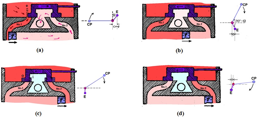
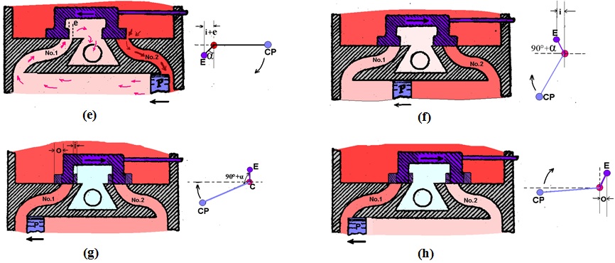
Fig. 34.6. Operations of expansion steam valve.

Fig. 34.7. p-V diagram for Expansive steam engines
Last modified: Wednesday, 11 September 2013, 4:48 AM