Site pages
Current course
Participants
General
MODULE - I
MODULE - II
MODULE - III
MODULE - IV
MODULE -V
MODULE - VI
MODULE - VII
MODULE - VIII
MODULE - IX
REFERENCES
LESSON - 41 INTRODUCTION TO COMPOUND STEAM ENGINES
41.1. COMPOUND STEAM ENGINES
In modern steam engines, the performance of steam engine is increased by using high pressure and temperature supply steam. However, by using higher steam supply pressure the range of expansion in steam engine cylinder is correspondingly increased as the condenser pressure remains the same. This large range of expansion in one cylinder causes
Large stroke of the piston which resulting in robust construction of engine,
Large temperature range
Heavy condensation of steam as the high pressure steam enters a relatively cold cylinder due to temperature range in one cylinder
To avoid above difficulties, the high pressure steam is allowed to expand in two or more cylinders. An engine with two or more cylinders for successive expansion of steam is termed as compound steam engine.
The compound steam engine of a simple steam power plant is shown in Fig 41.1. In a compound steam engine, the cylinder which receives steam directly from the boiler is known as high pressure (HP) cylinder and cylinder from which the steam is finally exhausted to the condenser is called the low pressure (LP) cylinder. The cylinders placed between HP and LP cylinders are called Intermediate pressure (IP) cylinders which may be one or more than one. In compound steam engine arrangement, the exhaust pressure for one cylinder is the inlet pressure for the next.
As high pressure steam from boiler expands in high pressure cylinder, hence, high-pressure cylinder requires small size. On other hand, as the low pressure steam exhausted from HP or IP cylinder expands in low-pressure cylinder, hence, a low-pressure cylinder requires large size.

Fig. 41.1. Compound steam engine of a simple power plant
Compound engines are found in capacity from 50 to 4,000 kW. They are used for marine service and for driving machines in mills.
41.2. CLASSIFICATION OF COMPOUND STEAM ENGINES
According to the number of expansion stages the compound steam engine is classified as under:
(i) Double expansion engine: The expansion is carried out in two cylinders. The exhaust steam from HP cylinder is admitted into LP cylinder.
(ii) Triple expansion engine: The expansion is carried out in three cylinders. The exhaust steam from HP cylinder is admitted into IP cylinder and then from the IP cylinder to the LP cylinder (Fig. 41.1).
(iii) Quadruple expansion engine: A four cylinder compound steam engine is called a quadruple expansion engine. In this, the exhaust steam from HP cylinder is admitted into a high pressure IP cylinder and then from high pressure IP cylinder to low pressure IP cylinder and finally from the low pressure IP cylinder to the LP cylinder.
41.3. THEORETICAL INDICATOR DIAGRAM OF COMPOUND STEAM ENGINE
The theoretical p-v diagram/indicator diagram for a triple expansion engine is shown in Fig. 41.2. In this diagram, the exhaust pressure ‘P1’ of HP cylinder is the inlet pressure of IP cylinder and the exhaust pressure’ P2’ of IP cylinder is the inlet pressure of LP cylinder.

Fig. 41.2. Theoretical diagram of a triple expansion engine
41.4. ADVANTAGES OF COMPOUND STEAM ENGINES
The advantages of compound steam engines are as listed below:
Refer Fig 41.2.
By reducing the pressure range to (pa-p1), (p1-p2) and (p2-pb) in HP, IP and LP cylinders of compound steam engine from pressure range (pa-pb) in single cylinder steam engine a more uniform temperature is maintained in each cylinder; this reduces the condensation and temperature stresses in each cylinder. This is so, because the difference between the highest and lowest temperatures of steam in each cylinder of compound steam engine is reduced as compare to highest and lowest temperatures of steam in single cylinder steam engine.
For same expansion from pressure Pa to Pb, the compound steam engine is much lighter in construction as compare to single cylinder steam engine. This is so, because the whole cylinder in single cylinder steam engine is required to make strong and large enough to withstand the initial high pressure steam ‘pa’ as well as to accommodate the large volume of low pressure steam. On other hand in compound steam engine, only the small high-pressure cylinder need to resist the initial high steam pressure ‘pa’ and the large low-pressure cylinder is designed to resist the low steam pressure.
As the early stages of condensation in H.P. and I.P. cylinder is followed by re-evaporation during their exhaust stroke, and thus, drier steam is admitted to the next low pressure cylinder for further expansion to back pressure.
Because of small pressure difference of (pa-p1), (p1-p2) and (p2-pb) in HP, IP and LP cylinders as compare to (pa-pb) in single cylinder engine, there is less leakage past the piston and valves in cylinder’s of compound steam engine.
The steam may be reheated between two cylinders of compound steam engine to seize the steam loss due to cylinder condensation.
As the cranks of two cylinders of compound steam engine are at 90 degree to each other; this will put the two cylinders out of phase, and thus lower the variation of turning moment; consequently, a lighter fly wheel will be needed.
Due to lighter reciprocating parts the engine vibration is reduced.
The engine may start in any position. This is a valuable asset in marine, locomotive and mining works.
The cost of compound steam engine, for the same power and economy, is less than that of a simple engine. This is so, because very light parts of compound steam engine are required as compared to single cylinder steam engine.
In the event of a breakdown, it is possible to run engine on reduced load by using only one cylinder.
41.5. DISADVANTAGES OF COMPOUND STEAM ENGINES:
(i) More complex system therefore it needs greater a tension and maintenance.
(ii) More lubrication troubles
(iii) More radiation loss.
41.6. METHODS OF COMPOUNDING STEAM ENGINES
Depending upon the arrangement of the cylinder and crank, compound steam engines are divided into two categories as follows: —

41.6.1. Tandem compounding steam engines
Tandem compound steam engine is shown in Fig. 41.3. In this engine, the pistons of H.P. and L.P. cylinders have a common piston rod, cross head, connecting rod and crank. This makes the stroke in both H.P. and L.P. cylinders in phase i.e. the operation in both the cylinders are same during forward stroke and return stroke. In addition to this, the axis of H.P. and L.P. cylinders is in the same straight line.
Flow path of steam
In Fig. 41.3(a), the flow path of steam in both HP and LP cylinders during forward stroke is shown by solid arrows. Since the steam engines are generally double acting, the steam flow in opposite direction in both cylinders during return stroke which is shown by dotted arrow heads in Fig 41.3(b).
During forward stroke, the high pressure steam from boiler enters on the left hand side of HP cylinder through valve ‘V1’ (Valve V3 closed) and the partial expanded steam on right side of H.P. cylinder, which is partially expanded in previous return stroke, is passed on to the left side of L.P. cylinder through valves V4 and V6 (Valves V2 and V5 closed), for further expansion of it to back pressure. At same time during same forward stroke, the steam on right side of L.P. cylinder, which is expanded to back pressure in previous return stroke, is exhausted through valve V8 (Valve V7 closed). This way one forward stroke is completed.


Fig. 41.3. Tandem Compound Steam Engine
During return stroke, the high pressure steam from boiler enters on the right side of H.P. cylinder through valve ‘V2’ (Valve V4 closed) and the partial expanded steam on left side of H.P. cylinder, which is partially expanded in previous forward stroke, is passed on to the right side of L.P. cylinder through valves V3 and V7 (Valves V1 and V8 closed), for further expansion to back pressure. At same time during same return stroke, the steam on left side of L.P. cylinder, which is expanded to back pressure in previous forward stroke, is exhausted through valve V5 (Valve V6 closed). This way one return stroke is completed.
HP, LP, and combined turning moments
As the stroke of H.P. and L.P. cylinders are in phase, the maximum and minimum turning moment on the crank shaft, due to each cylinder, will act at approximately the same crank angle as shown in Fig. 41.4. This results in a large variation at the maximum and minimum points of combined turning moment of H.P. and L.P. cylinders, and consequently, it needs a large flywheel. As the stroke of H.P. and L.P. cylinders are in phase, the balancing and vibration problems are more in this arrangement.

Fig. 41.4. Turning Moment Variation during Tandem Compounding.
41.6.2. Cross Compounding Steam Engines
41.6.2.1. Woolfe type:
Woolfe type two cylinder steam engine is shown in Fig. 41.5. In this engine, the pistons of H.P. and L.P. cylinders have separate piston rod, cross head, connecting rod and crank and the cranks of H.P. and L.P. cylinders are 180° out of phase. In addition to this, the axis of H.P. and L.P. cylinders is parallel to each other.
Flow path of steam
In Fig. 41.5 (a) , during forward stroke, the flow path of steam in both HP and LP cylinders is shown by solid arrows and during return stroke, it is shown by dotted arrow heads in Fig. 41.5 (b).


Fig. 41.5. Woolfe Type compound Engine
As the crank of two cylinders are 180° out of phase, this makes the time of exhaust of the H.P. cylinder coincide with the time of admission of L.P. cylinder. Therefore, the exhaust steam from H.P. cylinder would pass directly to the L.P. cylinder and hence both the cylinders are arranged side by side.
LP, HP and combined turning moments
The 180° out of phase cranks of HP and LP cylinders makes the turning moment of both cylinders in phase, for the whole cycle i.e. the maximum and minimum turning moment on the crank shaft due to H.P. and L.P. cylinders occur at approximately the same crank angle as shown in Fig. 41.6. This result in a large variation at the maximum and minimum points of combined turning moment of H.P. and L.P. cylinders and thus, the turning moment of Woolfe type compound steam engine is exactly similar to Tandem compounding steam engine. Due to large variation in combined turning moment, the Woolfe type Compounding Steam Engine also needs a large flywheel. As the stroke of H.P. and L.P. cylinders are 180° out of phase, the balancing and vibration problems are less.

Fig. 41.6. Turning Moment Variation for one cycle in Woolfe Type compound Engine
41.6.2.2. Receiver Type:
The receiver type compound steam engine is shown in Fig. 41.7. In this engine like Woolfe type compound engine, the pistons of H.P. and L.P. cylinders have separate piston rod, cross head, connecting rod and crank but the cranks of H.P. and L.P. cylinders are 90° out of phase. This 90° out of phase cranks makes the forward and return strokes of H.P. and L.P. cylinders out of phase as shown in Fig. 41.7. In this, the axis of H.P. and L.P. cylinders is parallel to each other.
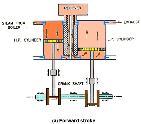

Fig. 41.7. Receiver Type Compound Steam Engines
Flow path of steam
As the strokes of the two cylinders in Receiver Type compound steam engine are out of phase, the high pressure steam from H.P. cylinder cannot be exhausted directly into the L.P. cylinder. Instead, the high pressure steam from H.P. cylinder is first exhausted into a vessel called a receiver then it is exhausted into LP cylinder when it is ready to receive the steam. The receiver is placed between the H.P. and L.P. cylinders. During the stroke, the receiver pressure varies depending upon supply and demand of steam from it. In order to reduce this pressure variation, the receiver is made at least 1.5 times the H.P. cylinder volume. The pressure variation in the receiver due to pressure drop as a result of condensation can also be reduced by steam jacketing the receiver.
LP, HP and combined turning moments
Fig. 41.8 shows the LP cylinder, HP cylinder and combined HP-LP cylinder turning moment variation. The 90° out of phase cranks of receiver type compounding steam engine makes the turning moment of HP cylinder and LP cylinder on the crank shaft out of phase by 90°, for the whole cycle i.e. the maximum and minimum turning moment in H.P. and L.P. cylinders occur at out of phase by approximately 90° crank angle as shown in Fig. 41.6. This makes the whole cycle more uniform and consequently, it needs a smaller flywheel. Thus, the balancing and vibration problems are less in this arrangement. This is the chief advantages of the receiver type arrangement.

Fig. 41.8. Turning moment variation for one cycle in Receiver Type Compound Steam Engines
Last modified: Wednesday, 11 September 2013, 5:58 AM