Site pages
Current course
Participants
General
MODULE 1. Orhtographic Projections of Machine comp...
MODULE 2. Types of joints
MODULE 3. Computer Aided drawing
MODULE 4. Numeric control systems
Topic 5
Topic 6
Topic 7
Topic 8
Topic 9
Topic 10
LESSON 13. B-spline and Bezier curves and Geometric modeling techniques, wire frames
13.1.Introduction
In early days, the drawing of curves of done by using splines which is a long flexible piece of wood or plastic. In the 1960s a mathematician and engineer named Pierre Bezier changed everything with his newly developed CAGD tool called UNISURF. This new software allowed designers to draw smooth looking curves on a computer screen, and used less physical storage space for design materials. Beziers contribution to computer graphics has paved the road for CAD software. His developments serve as an entry gate into learning about modern computer graphics, which spawned a relatively new mathematical object known as a spline, or a smooth curve specified in terms of a few points.
13.2.B-spline and Bezier curves
In the mathematical subfield of numerical analysis, a B-spline is a spline function that has minimal support with respect to a given degree, smoothness, and domain partition. A fundamental theorem states that every spline function of a given degree, smoothness, and domain partition, can be uniquely represented as a linear combination of B-splines of that same degree and smoothness, and over that same partition.
The term "B-spline" is short form for basis spline. B-splines can be evaluated in a numerically stable way by the de Boor algorithm. In the computer science subfields of computer-aided design and computer graphics., A B-spline is simply a generalisation of a Bezier.
Bezier curves are widely used in computer graphics to model smooth curves. As the curve is completely contained in the convex hull of its control points, the points can be graphically displayed and used to manipulate the curve intuitively. Affine transformations such as translation, and rotation ie., a transformation which preserves straight lines (i.e., all points lying on a line initially still lie on a line after transformation) and ratios of distances between points lying on a straight line (e.g., the midpoint of a line segment remains the midpoint after transformation). It does not necessarily preserve angles or lengths, but does have the property that sets of parallel lines will remain parallel to each other after an affine transformation. Bezier curves are parametric functions, and are characterised by using the same kind of function for all its dimensions. Unlike the above example, where the x and y values use different functions (one uses a sine, the other a cosine), Bézier curves use "binomial polynomials" for both x and y.
Bezier curves are polynomials of t, rather than x, with the value for t fixed being between 0 and 1, with coefficients a, b etc. taking the "binomial" form, pretty simple description for mixing values:
Linear - t+(1−t)
Square -t2+2⋅(t⋅(1−t))+(1−t)2
Cubic -t3+3⋅(t2⋅(1−t))+3⋅(t⋅(1−t)2)+(1−t)3
13.3.Geometric modelling
Geometric modelling is a branch of applied mathematics and computational geometry that studies methods and algorithms for the mathematical description of shapes.
The shapes studied in geometric modelling are mostly two- or three-dimensional, although many of its tools and principles can be applied to sets of any finite dimension. Today most geometric modelling is done with computers and for computer-based applications. Two-dimensional models are important in computer typography and technical drawing. Three-dimensional models are central to computer-aided design and manufacturing (CAD/CAM), and widely used in many applied technical fields such as civil and mechanical engineering, architecture, geology and medical image processing.
Geometric models are usually distinguished from procedural and object-oriented models, which define the shape implicitly by an opaque algorithm that generates its appearance. They are also contrasted with digital images and volumetric models which represent the shape as a subset of a fine regular partition of space; and with fractal models that give an infinitely recursive definition of the shape. However, these distinctions are often blurred: for instance, a digital image can be interpreted as a collection of colored squares; and geometric shapes such as circles are defined by implicit mathematical equations. Also, a fractal model (mathematical set) yields a parametric or implicit model when its recursive definition is truncated to a finite depth.
13.4.Wire frames
A wire frame is a visual presentation of a three dimensional or physical object used in 3D computer graphics. It is created by specifying each edge of the physical object where two mathematically continuous smooth surfaces meet, or by connecting an object's constituent vertices using straight lines or curves. The object is projected onto the computer screen by drawing lines at the location of each edge. The term wireframe comes from designers using metal wire to represent the 3 dimensional shape of solid objects.3D wireframe allows to construct and manipulate solids and solid surfaces. 3D solid modeling technique efficiently draws high quality representation of solids than the conventional line drawing. A wire frame model allows visualization of the underlying design structure of a 3D model. Traditional 2-dimensional views and drawings can be created by appropriate rotation of the object and selection of hidden line removal via cutting planes.
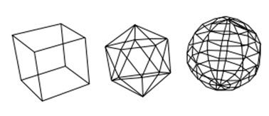
Fig.13.1.Wire frame
The wire frame format is also well suited and widely used in programming tool paths for DNC (Direct Numerical Control) machine tools.
Last modified: Monday, 16 September 2013, 7:18 AM