Site pages
Current course
Participants
General
MODULE 1. Orhtographic Projections of Machine comp...
MODULE 2. Types of joints
MODULE 3. Computer Aided drawing
MODULE 4. Numeric control systems
Topic 5
Topic 6
Topic 7
Topic 8
Topic 9
Topic 10
LESSON 16. NC machine tools and control units, tooling for NC machines, part programming, punched tape coding and format, Manual and computer assisted programming
16.1.Introduction
NC machine tools require a sequence of instructions that are to be given to the machine through machine language. For this programs are to be written and fed to the machine. This may be done either manually or by using computers. A understanding of the basics of this concept is necessary when we go for CAD/CAM
16.2.NC machine tools and control units
Any machine tool, controlled by numeric control is a NC machine tool. The control units may be open loop or closed loop.
16.2.1.Open Loop Control Systems
The open-loop control means that there is no feedback and uses stepping motors for driving the leadscrew . A stepping motor is a device whose output shaft rotates through a fixed angle in response to an input pulse . The accuracy of the system depends on the motor's
ability to step through the exact number. The frequency of the stepping motor depends on the
load torque. The higher the load torque, lower would be the frequency . Excessive load torque
may occur in motors due to the cutting forces in machine tools . Hence this system is more suitable for cases where the tool force does not exist.
16.2.2. Closed-loop Control Systems
Closed -loop NC systems are appropriate when there is a force resisting the movement of the tool or work piece . In these systems, servomotors and feedback devices are used to ensure that the desired position is achieved. The feedback sensor may be an optical encoder. The encoder consists of a light source, a photo detector, and a disk containing a series of slots. The encoder is connected to the leads crew . As the screw turns, the slots cause the light to be seen by the photodetector as a series of flashs which are converted into an equivalent series of electrical pulses which are then used to characterize the position and the speed.
16.3.Tooling for NC machines
For effective utilization of CNC machines it is important to consider the selection and usage of tooling, namely tool holders, cutting tools and work holding devices. The tools for CNC machines must be quickly changeable to reduce non-cutting time, preset and reset outside the machine, high degree of interchangeability, increased reliability and high rigidity.
The cutting tools can be classified on the basis of setting up of tool, tool construction and cutting tool material :
On the Basis of Setting up of Cutting Tool
(a) Preset tools.
(b) Qualified tools.
(c) Semi qualified tools.
On the Basis of Cutting Tool Construction
(a) Solid tools.
(b) Brazed tools.
(c) Inserted bit tools.
On the Basis of Cutting Tool Material
(a) High speed steel (HSS).
(b) High carbon tool steel (HCS).
(c) Cast alloy.
(d) Cemented carbide.
(e) Ceramics.
(f) Boraon Nitride.
(g) Diamond.
(h) Sialon
The following points are to be considered while designing of CNC tooling :
(a) To give High accuracy.
(b) For variety of operations.
(c) Interchangeability to produce same accuracy.
(d) Flexibility.
(e) Rigidity of tooling to withstand cutting forces.
(f) Rigidity to transmit the power at higher speeds.
(g) Quick changing of tools to keep the down time minimum.
16.4. Work Holding Devices For CNC Machines
In the CNC machines, fixtures are still required to locate and hold the work pieces while machining. The work holding devices should have the following uniqueness :
a) Work holding devices must have required accuracy and must have matching
reference surfaces with the reference system.
(b) Work holding devices are allowed to perform a number of operations on different faces
in a single setting.
(c) Work holding devices must enable quick loading and unloading.
(d) Work holding devices must be fool-proofing to avoid incorrect loading of the job.
(e) Work holding devices must be sufficient rigidity to fully withstand the cutting forces.
(f) Work holding devices must be safe in use and loading and unloading.
(g) Work holding devices must have a sufficient of clamping force for use of full roughing
cuts.
(h) Work holding devices must be simple in construction maximum as possible.
16.5.Part programming
Numerical control part programming is the procedure by which the sequence of processing steps to be performed on the NC machine is planned and documented. It involves the preparation of a punched tape (or other input medium) used to transmit the processing instructions to the machine tool. There are two methods of part programming: manual part programming and computer-assisted part programming.
16.6.Punched tape coding and format
Punched tape or perforated paper tape is a form of data storage, consisting of a long strip of paper in which holes are punched to store data. Now effectively obsolete, it was widely used during much of the twentieth century for teleprinter communication, for input to computers of the 1950s and 1960s, and later as a storage medium for minicomputers and CNC machine tools.
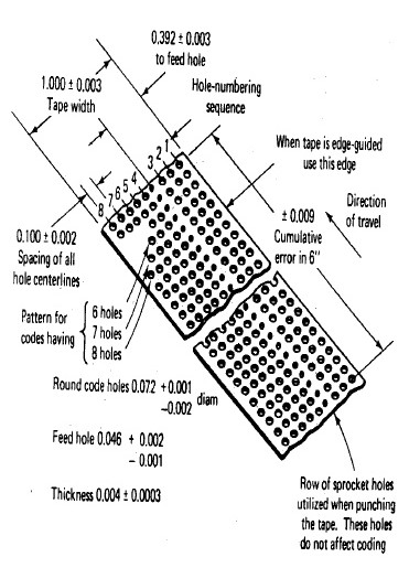
Fig.16.1. Punched tape format
There are two basic methods of preparing the punched tape. The first method is manual part programming and involves the use of a typewriter like device..The operator types directly from the part programmer's handwritten list of coded instructions. This produces a typed copy of the program as well as the punched type. The second method is computer-assisted part programming. By this approach, the tape is prepared directly by the computer using a device called a tape punch.
16.7. Manual and computer assisted programming
16.7.1. Manual part programming
The part program is a sequence of instructions, which describe the work, which has to be done on a part, in the form required by a computer under the control of a numerical control computer program. It is the task of preparing a program sheet from a drawing sheet. All data is fed into the numerical control system using a standardized format.
Programming is where all the machining data are compiled and where the data are translated into a language which can be understood by the control system of the machine tool. The machining data is as follows :
(a) Machining sequence classification of process, tool start up point, cutting
depth, tool path, etc.
(b) Cutting conditions, spindle speed, feed rate, coolant, etc.
(c) Selection of cutting tools.
The steps involved in preparing the part program are,
(a) The start up procedure is determined, which includes the extraction of dimensional data
from part drawings and data regarding surface quality requirements on the machined
component.
(b) The tool is selected and the tool offset is determined.
(c) The zero position is set up for the workpiece.
(d The speed and rotation of the spindle is selected.
(e) The tool motions are set up according to the profile required.
(f The cutting tool is returned to the reference point after completion of work.
(g) The program is closed stopping the spindle and coolant.
16.7.2. Computer assisted programming
If the complex-shaped component requires calculations to produce the component are
done by the programming software contained in the computer. The programmer communicates with this system through the system language, which is based on words. There are various programming languages developed in the recent past, such as APT (Automatically Programmed Tools) is used for writing a computer programme, which has English like statements. A translator known as compiler program is used to translate it in a form acceptable to MCU.
The programmer has to do only following things :
(a) Define the work part geometry.
(b) Defining the repetition work.
(c) Specifying the operation sequence.
Last modified: Monday, 16 September 2013, 7:36 AM