Site pages
Current course
Participants
General
MODULE 1.
MODULE 2.
MODULE 3.
MODULE 4.
MODULE 5.
MODULE 6.
MODULE 7.
MODULE 8.
MODULE 9.
MODULE 10.
MODULE 11.
MODULE 12.
LESSON 7. Welded Connection
7.1 INTRODUCTION
The development of welding technology in 1940s has considerably reduced the riveted joint applications. Welding is the method of locally melting the metals (sheets or plates – overlapping or butting) with intensive heating along with a filler metal or without it and allowing cooling them to form a coherent mass, thus creating a joint. A typical weld showing various zones of weld is shown in Fig. 7.1. Such joints can be created to make structures, boilers, pressure vessels, etc. and are more conveniently made in steel. The progress has been made in welding several types of steels, but large structure size may impede the use of automatic techniques and heat treatment which becomes necessary in some cases. Welded ships were made in large size and large number during Second World War and failures of many of them spurted research efforts to make welding a better technology.

7.2 ADVANTAGES OF WELDED CONNECTIONS
The gross sectional area of the welded members is effective since the welding process does not involve drilling holes.
Welded structures are comparatively lighter than corresponding riveted structures.
A welded joint has a greater strength sometimes equal to the strength of the parent metal itself.
Repairs and further new connections can be done more easily than in riveting.
Welded joints provide rigidity leads to smaller bending moments than corresponding riveted members.
Welded joints are economical to riveted joints due to low maintenance cost.
Members of such shapes that afford difficulty for riveting can be more easily welded.
A welded structure has a better finish and appearance than the corresponding riveted structure.
Connecting angles, gusset plates, splicing plates can be minimized.
Steel bars in reinforced concrete structure may be welded easily so that lapping of bars may be avoided.
It is possible to weld at any point at any part of a structure, but riveting will always require enough clearance.
The process of welding does not involve great noise compared to the noise produced in the riveting process.
7.3 DISADVANTAGES OF WELDED CONNECTIONS
Welding requires skilled labor and supervision.
Testing a welded joint is difficult. An X-ray examination alone can enable us to study the quality of the connection.
Due to uneven heating and cooling, the welded members are likely to get warped at the welded surface.
Internal stresses in the welded zones are likely to be set up.
7.4 TYPES OF WELDED JOINTS
Welds may be classified into two main types namely butt-weld and fillet-weld.
7.4.1. Butt weld
This type of weld is used when the members are in same plane. Butt weld is also termed as groove weld. The butt weld is used to join structural members carrying direct compression or tension. It is used to make tee-joint and butt-joint. The following types of butt welds are in practice. These are named depending upon shape of the grove made for welding.
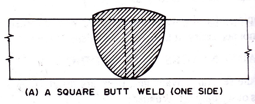
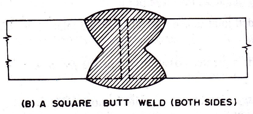
i. Square butt weld.
A square butt weld is a weld in the preparation of which the fusion faces lie approximately at right angles to the surfaces of the components to be joined and are substantially parallel to one another (Fig. 7.2 a & b).
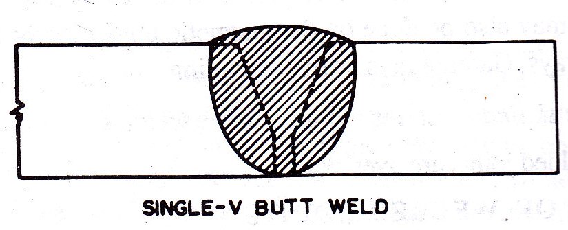
ii.Single V-butt weld
A single V-butt weld is a weld in the preparation of which the edges of both components are prepared so that in the cross-section, the fusion faces form a V as shown in Fig. 7.3.
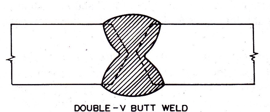
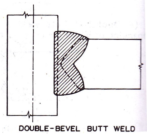
iii.Double V-butt weld
A double V-butt weld is a weld in the preparation of which the edges of both components are double beveled so that in cross-section, the fusion faces form two opposing V’s as shown in Fig. 7.4.
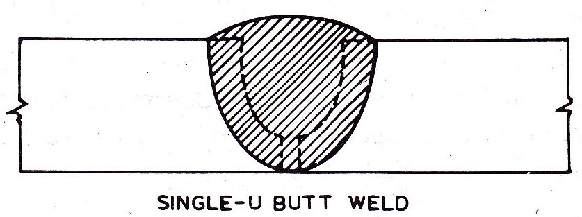
iv. Single U-butt weld
A single U-butt weld is a weld in the preparation of which the edges of both components are prepared so that in the cross section, the fusion faces form a U as shown in Fig. 7.5.
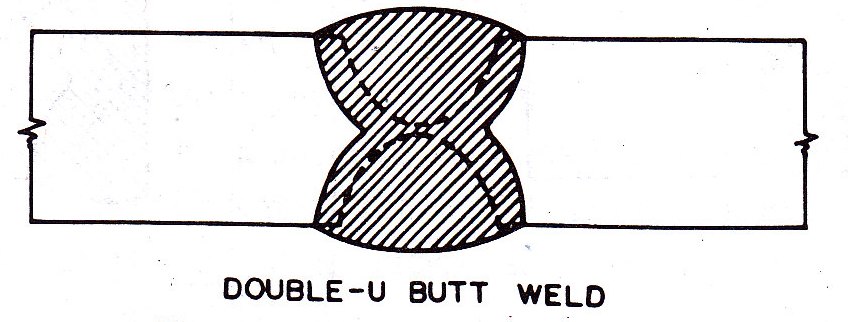
v. Double U-butt weld
A double U-butt weld is a weld in the preparation of which the edges of both components are prepared so that in the cross section, the fusion faces form two opposing U’s as shown in Fig. 7.6.
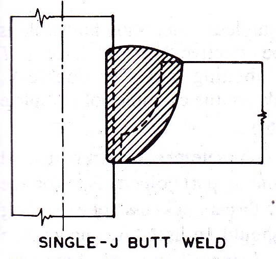
vi.Single J-butt weld
A single J-butt weld is a weld in the preparation of which the edges of one component are prepared so that in the cross section, the fusion faces is in the form a J and the fusion face of the other component is at right angles to the surface of the first component as shown in Fig. 7.7.
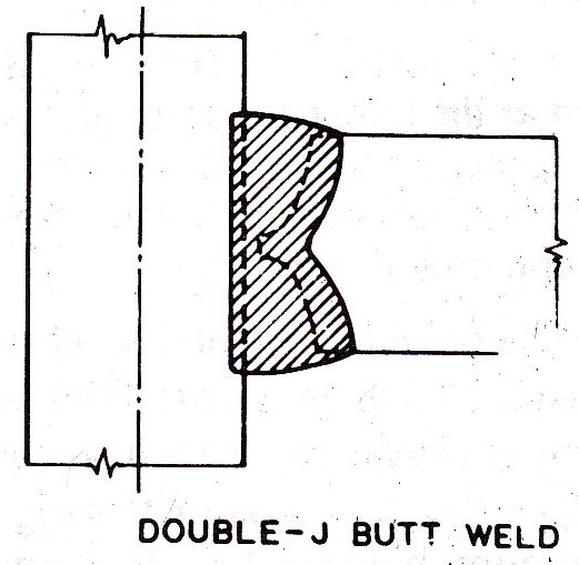
vii.Double J-butt weld
A double J-butt weld is a weld in the preparation of which the edges of one component are prepared so that in the cross section, the fusion faces is in the form of two opposing J’s and the fusion face of the other component is at right angles to the surface of the first component as shown in Fig. 7.8.
viii.Single bevel butt weld
A single bevel butt weld is a weld in the preparation of which the edge of one component is beveled and the fusion face of the other component is at right angles to the surface of the first component as shown in Fig. 7.9.

ix.Double bevel butt weld
A double bevel butt weld is a weld in the preparation of which the edges of one component are double beveled and the fusion face of the other component is at right angles to the surface of the first component as shown in Fig. 7.10.
7.4.2. Specifications of the butt weld
i. Size of butt weld
The size of a butt weld is specified by the effective throat thickness. The effective throat thickness in case of complete penetration butt weld is taken as the thickness of thinner part joined. The double V, double U, double J and double bevel butt welds are the examples of complete penetration butt weld.
The effective throat thickness in case of incomplete penetration butt weld is taken as 7/8th of the thickness of the thinner part joined. But for the purpose of stress calculation, a required effective throat thickness not exceeding 5/8th of the thickness of thinner part joined should be used. An incomplete penetration butt weld is also termed as unsealed single butt weld. Single V, Single U, Single J, Single bevel butt joints are the examples of incomplete penetration butt weld. In incomplete penetration butt weld, the weld metal is not deposited intentionally through the full thickness of the joint. The unwelded portion in incomplete penetration butt weld, welded from both sides shall not be greater than 1/4th of the thickness of thinner part joined and should be central in the depth of the weld.
The unsealed butt welds V, U, J and bevel types and incomplete penetration butt welds should not be used for highly stressed joints and joints subjected to dynamic, repeated or alternating forces. The shall also not be subjected to a bending moment about the longitudinal axis of the weld other than that normally resulting from the eccentricity of the weld metal relative to the parts joined.
ii. Effective length of butt weld
The effective length of butt weld is the length for which the specified size (throat thickness) of the weld exists.
iii. Effective area of butt weld
The effective area of a butt weld is taken as the product of the effective throat thickness and the effective length of butt weld.
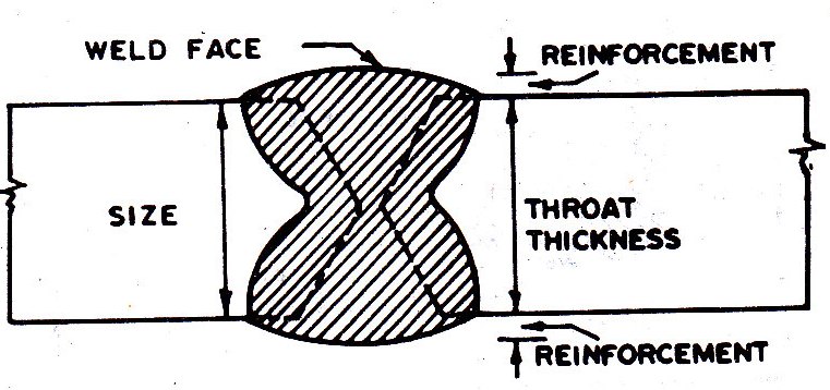
iv. Reinforcement
The extra metal deposited above the surface of the parent metal as shown in Fig. 7.11 is called reinforcement. This reinforcement is provided to give sufficient surfaces convexity and to ensure full effectiveness at the joint. This requires a minimum practical surface convexity of 1.0 mm. This reinforcement should not exceed 3.0 mm. This is not considered as part of throat thickness. This reinforcement may also be removed if a flush surface is desired.
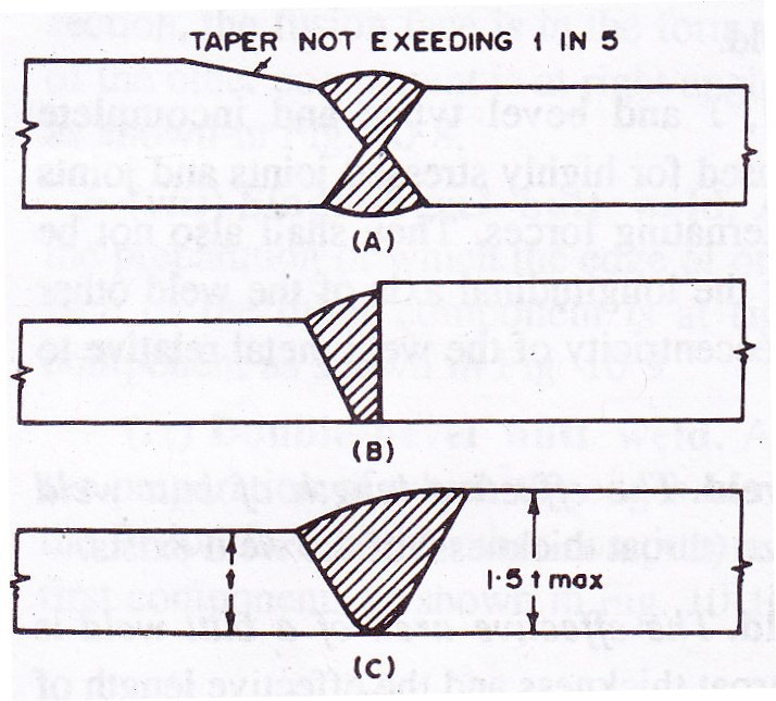
When the structural members of unequal thickness are butt welded and difference in thickness of members exceeds 25 per cent of the thinner part or 3.0 mm in metal arc welding and 6.0 mm or more in oxy-acetylene welding, the thicker part is beveled so that the slop of the surface from one part to the other is not steeper than one in five as shown in Fig. 7.12.A. Where this arrangement is not practicable, the weld metal should be built-up at the junction with the thicker part to dimension at least 25 per cent greater than that of the thinner part in metal arc welding as shown in 7.12.B. alternatively, the weld metal should be built-up to the dimensions of thicker members as shown in 7.12.C. In case of complete penetration butt weld, generally, deign calculations are not necessary, as these will usually provide the strength at the joint equal to the strength of the member connected.
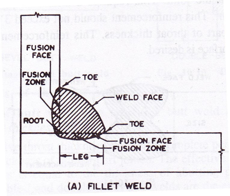
7.4.3 Fillet-weld
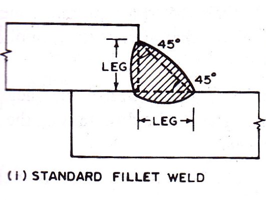
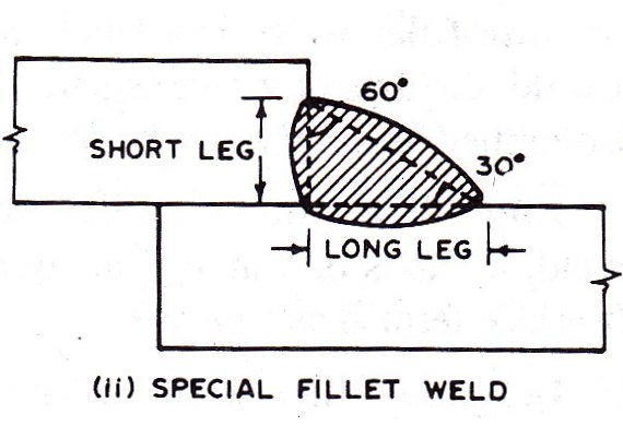
This type of weld is used when the members to be connected overlap each other. A fillet weld is a weld of approximately triangular cross section joining two surfaces approximately as right angles to each other in lap joint or tee joint. A fillet weld is shown in Fig. 7.13.A. When the cross section of fillet weld is 45˚, isosceles triangle as shown in Fig. 7.13.B.I, it is known as a standard fillet weld. The standard 45˚ fillet weld is generally used. When the cross section of the fillet weld is 30˚ and 60˚ triangle as shown in Fig. 7.13.B.II, it is known as a special fillet weld.
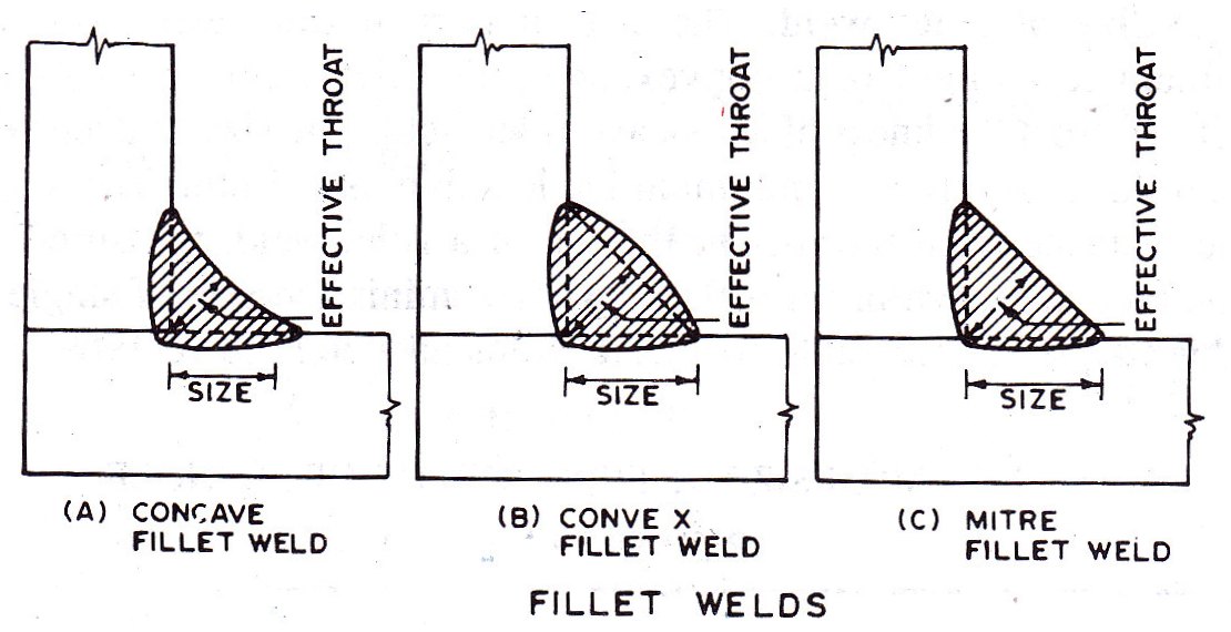
A fillet weld is termed as concave fillet weld or convex fillet weld or mitre fillet weld depending on the weld face in concave or convex or approximately flat as shown in Fig. 7.14, respectively. A fillet weld is termed as normal fillet weld or deep penetration fillet weld depending upon the depth of penetration beyond the root is less than 2.4 mm or more respectively.
The fillet welds are of three types as shown in Fig. 7.15.
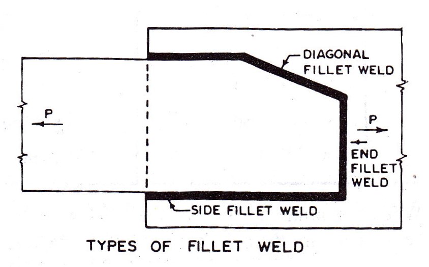
i.Side fillet weld
It is fillet weld stressed in longitudinal shear, i.e., a fillet weld, the axis of which is parallel to the direction of these applied loads. It is also termed as longitudinal fillet weld.
ii.End fillet weld
It is a fillet weld stressed in transverse shear, i.e., a fillet weld, the axis of which is at right angles to the direction of the applied load. It is also termed as transverse fillet weld.
iii.Diagonal fillet weld
It is a fillet weld the axis of which is inclined to the direction of the applied load
A fillet weld is placed on the sides or end of the base metal and it is subjected to shear along with tension or compression and usually bending.
7.4.4 Specification of fillet weld
i. Size of fillet weld
The size of normal fillet weld is specified as minimum leg length of a convex or mitre fillet weld or 1.414 times the effective throat thickness of a concave fillet weld. The size of deep penetration fillet weld is specified as minimum leg length plus 2.4 mm. the length of leg is the distance from the root to the toe of a fillet weld, measured along the fusion face.
The International Standard code has recommended the minimum size of the weld. If the thickness of thicker part is up to 10 mm, the minimum size of the welding is 3 mm. If the thickness of thicker part is in between 10 mm to 20 mm, the minimum size of the welding is 5 mm. If the thickness of thicker part is in between 20 mm to 32 mm, the minimum size of the welding is 6 mm. If the thickness of thicker part is above 32 mm, the minimum size of the welding is 10 mm. When the minimum size of the fillet weld is greater than the thickness of the thinner part, the minimum size of the weld should be equal to the thickness of thinner part. Where the thicker part is more than 50 mm, special precaution like preheating will have to be taken.
ii. Effective throat thickness
The effective throat thickness of a fillet weld is the perpendicular distance from the root to the hypotenuse of the largest isosceles right angled triangle that can be inscribed within the weld cross section. The effective throat thickness of a fillet weld shall not be less than 3 mm and shall generally not exceed 0.7 times the thickness of thinner part and equal to the thickness of thinner part under special circumstances.
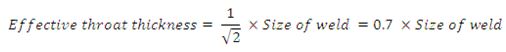
In general, for the purpose of stress calculation,
![]()
Where K is a constant. The value of K for different angles between fusion faces is adopted as per Table 7.1 as recommended in IS:816-1969
TABLE 7.1. VALUE OF K FOR DIFFERENT ANGLES BETWEEN FUSION FACES
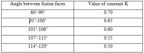
A fillet weld is not used for joining parts, if the angle between fusion faces is greater than 120˚ or less than 60˚.
iii.Effective length
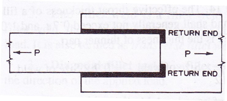
The effective length of the weld is the length of the weld for which the specified size and throat thickness i.e., correctly proportioned cross section of the weld, exist. It is taken as the actual length minus twice the size of weld, since the specified size and throat thickness do not exist at the ends. The effective length of the weld is shown on the drawings. In practice the actual length of weld is made equal to the effective length shown on the drawing plus twice the weld size. The effective length of fillet weld should not be less than four times the size of the weld.
When the ends are returned as shown in Fig. 7.16, then the ends should be carried continuous around the corners for distance not less than twice the size of weld. This should be applied particularly to side and top fillet weld in tension.
iv.Effective area
The effective area of a fillet weld is taken as the product of effective length and effective throat thickness.
7.5 WORKING STRESSES IN WELDS
Working stresses in welds, when welded joints are constructed with mild steel conforming to IS:226-1962 as parent metal and with electrodes conforming to IS:814-1974 are adopted as per Table 7.2 are recommended in IS:816-1969.
TABLE 7.2 WORKING STRESSES IN WELDS
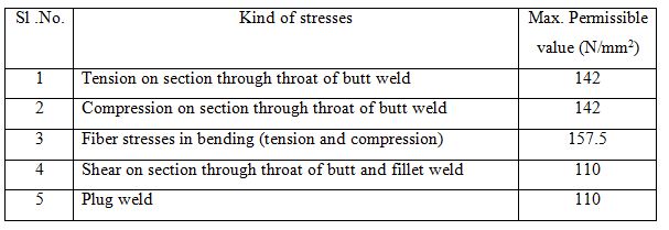
The maximum permissible value of stresses of shear and tension are reduced to 80 per cent of those given in Table 7.2, in case, the welding is done at site. When the effects of wind or earthquake forces are considered, then, maximum permissible values of stresses are increased by 25 per cent. It is to note that maximum permissible stresses given in the Table 7.2 are same as for the parent metal (mild steel IS:226-1962).
7.6 DESIGN OF WELDED JOINTS SUBJECTED TO AXIAL LOAD
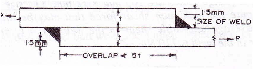
The complete penetration butt weld does not require design calculations. In case of incomplete penetration butt weld, effective throat thickness of the weld is computed and welding is done up to the required length. In case of fillet weld, size of the weld is fixed keeping in view the minimum size of the weld as per IS:816-1969 recommends that when filet weld is applied to the square edge of member, the maximum size of weld should be less than the edge thickness by at least 1.5 mm as shown in Fig. 7.17. This avoids the washing down of edges of weld. When fillet weld is applied to the round toe of rolled steel sections, the maximum size of the weld should not exceed ¾ of the thickness of the section at the toe. When fillet weld is used for lap joint, then overlap of the members connected as shown in Fig. 7.17, should not be less than five times thickness of thinner part.
The strength of the fillet weld is determined per mm length for the size of the weld adopted. The effective length of the weld is then computed for the pull or thrust to be transmitted by the weld. In case, only side fillet welds are applied, the length of the each weld should not be less than perpendicular distance between them and spacing between them shall not be more than 16 times the thinner part.
Example 7.1. Two plates 16 mm thick are joined by i. a double U butt weld, ii. A single U butt weld. Determine the strength of the welded joint in tension in each case. Effective length of weld is 150 mm. Allowable stress in butt weld in tension is 142 N/mm2.
Solution
i.In case of double U but weld, complete penetration of weld takes place
Effective throat thickness of weld = 16 mm
Effective length of weld = 150 mm
Strength of single U butt weld = throat thickness x length of weld x permissible shear stress
= (16 x 150 x 142/1000) = 340.8 kN
ii.In case of single U butt weld, incomplete penetration of butt weld takes place
Effective throat thickness = 5/8 x 16 = 10 mm
Effective length of weld = 150 mm
Strength of single U butt weld = (10 x 150 x 142/1000) = 213.0 kN
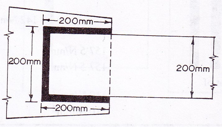
Example 7.2. In a truss girder of a bridge, a tie as shown in Fig. 7.18 is connected to the gusset plate by fillet weld. Determine the strength of the weld. The size of the weld in the fillet weld is 6 mm.
Solution
Size of weld = 6 mm
Effective throat thickness = 0.7 x 6 = 4.2 mm
Effective length of fillet weld = 200 + 200+ 200 = 600 mm
Strength of fillet weld = (4.2 x 600 x 110/1000) = 277.2 kN
Example 7.3. In Example 7.2, the pull to be transmitted by the tie is 300 kN. Determine the necessary overlap of the tie.
Solution
Size of weld = 6 mm
Effective throat thickness = 4.2 mm
Pull transmitted by the end fillet weld = (4.2 x 200 x 110/1000) = 92.4 kN
Let l be the necessary overlap required, the pull transmitted by the side fillet is
= (4.2 x 2 x l x 110/1000) = 0.924 l kN
Total pull transmitted = 92.4 + 0.924 l = 300 kN
Therefore, the necessary overlap of the tie l = 224.7 mm.
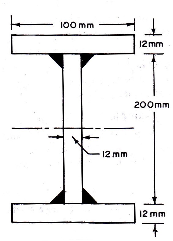
Example 7.4. The web plate of a built-up welded I-section is 200 mm x 12 mm and the flange plates are 100 mm x 12 mm. The size of fillet weld is 6 mm. Compute the maximum shear force that may be allowed at any section, if the average allowable shear in the web is 0.4 fy and maximum allowable shear in the weld is 110 N/mm2.
Solution
Moment of inertia of the built-up section (about xx axis)
Ixx = 1/12[10 x 22.43 – 8.8 x 203] x 104 = 3499.52 x 104 mm4
Intensity of shear stress (at weld section)
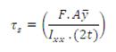
Where, 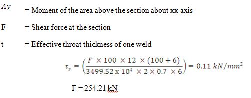
The average shear stress in the web is 0.4 x 250 N/mm2.
Allowable shear force in the web F1=(200 x 12 x 0.4 x 250/1000) = 240 kN.
The design drawing is Fig. 7.19.
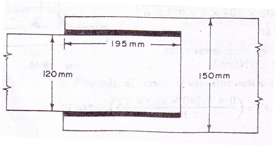
Example 7.5. Design a suitable longitudinal fillet weld to connect the plates as shown in Fig. 7.20 and to transmit a pull equal to the full strength of thin plate. Allowable stress in the weld is 110 N/mm2 and tensile stress in the plate 0.6 fy N/mm2. The plates are 10 mm thick.
Solution
The minimum size of weld required for thickness up to 20 mm is 5 mm. The maximum size of fillet weld is limited by the thickness of the plate is (10-1.5)=8.5 mm. Provide 6 mm fillet weld.
Pull transmitted by 1 mm weld = (1 x 0.7 x 6 x 110/1000) = 0.462 kN
Tensile strength of thin plate = (120 x 10 x 0.6 x 250/1000) = 180 kN
Necessary length of the weld = (180 / 0.462) = 389.61 mm
Provide 195 mm longitudinal weld on each side.
Check: Length of the weld 195 mm is greater than perpendicular distance 120 mm between welds
Example 7.6. Two plates 120 mm x 10 mm are overlapped and connected together by transverse fillet weld to transmit pull equal to full strength of the plate. Design the suitable welding. Allowable stress in the weld is 110 N/mm2. Allowable stress in tension in the plate is 0.6 fy N/mm2.
Solution
Minimum size of weld = 5mm
Maximum size of weld = (10-1.5) = 8.5 mm
Total length of two welds = 240 mm
Total load transmitted by 6 mm weld = (240 x 0.7 x 6 x 110/1000) = 110.88 kN
Maximum pull that can be transmitted by the plate = (120 x 10 x 0.6 x 250/1000) =180 kN
To transmit the pull equal to the full strength of plate, provide additional weld by plug weld. Provide two rectangular plug welds 30 mm x 15 mm as shown in Fig. 7.21 which satisfies the specification.
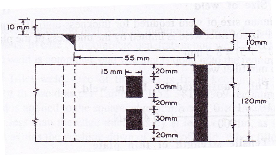
Strength of two plug welds = (2 x 30 x 15 x 110/1000) = 99 kN.
Total pull now transmitted = (110.88 + 99) = 209.88 kN > 180 kN. Hence satisfactory.
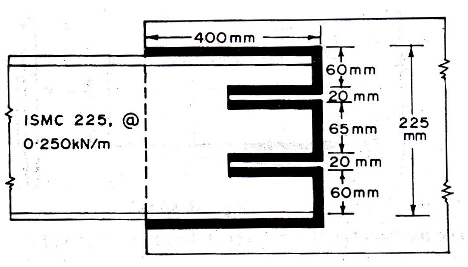
Example 7.7. A tie member consists of two MC 225, @ 0.250 kN/m. The channels are connected to either side of a gusset plate 12 mm thick. Design the welded joint to develop the full strength of the tie. The overlap limited to 400 mm.
Solution
From ISI Handbook No. 1, for MC 225, @ 0.250 kN/m
Thickness of web = 6.4 mm
Thickness of flange = 12.4 mm
Sectional area = 3301 mm2
Tensile strength of each channel section = (3301 x 0.6 x 250/1000) = 495.15 kN
Provide 4 mm weld
Strength of weld per mm length = (1 x 0.7 x 4 x 110/1000) = 0.308 kN
Total length of fillet weld necessary to connect one channel section = (495.15/0.308)
= 1607.6 mm
The overlap of channe is limited to 400 mm. the width of slot should not be less than 3 times thickness (3 x 6.4 = 19.2 mm). Provide two slots 20 mm side. The distance between edge of the slot and edge of channel or between adjacent slots also should not be less than twice the thickness (2x6.4=12.8 mm). Provide these distances as shown in Fig. 7.22. Let x be the length of the slot.
The total length of the weld = 800 + 225 + 4x – 2x20 = 1607.6 mm
Therefore, the length of the slot x = 155.65 mm ≈ 160 mm long fillet welding is done as shown in Fig. 7.22.
Last modified: Saturday, 5 October 2013, 7:30 AM