Site pages
Current course
Participants
General
MODULE 1.
MODULE 2.
MODULE 3.
MODULE 4.
MODULE 5.
MODULE 6.
MODULE 7.
MODULE 8.
MODULE 9.
MODULE 10.
MODULE 11.
MODULE 12.
LESSON 8. Tension Member
8.1 INTRODUCTION
A tension member is a member which carries mainly a tensile force in the direction parallel to its longitudinal axis. A tension member is also called as a tie member or simply a tie. In some cases tension member also subjected to bending either due to eccentricity of the longitudinal load or due to transverse loads acting in addition to the main longitudinal load. A tension member is one of the most commonly occurring types of structural members. Tension members may occur either as minor tension members such as bars, flats, rods etc. or as major tension members of roof and bridge trusses
8.2 MINOR TYPES OF TENSION MEMBERS
The minor types of tension members are shown in Fig. 8.1.
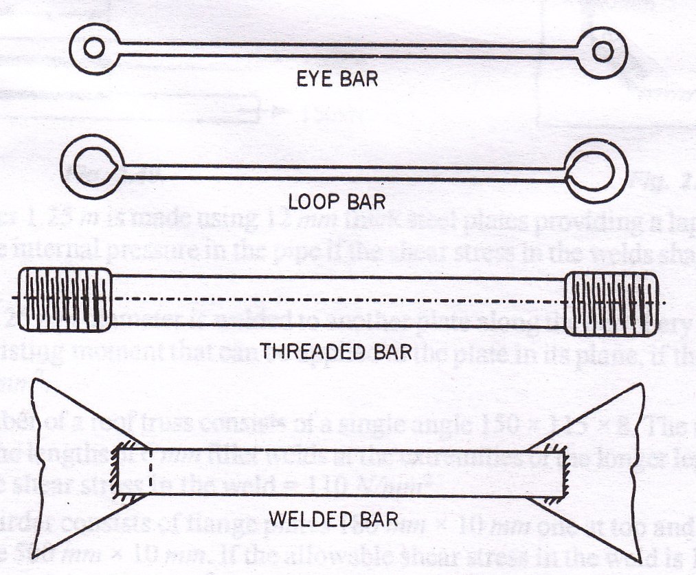
i.Eye-bars
These members are used where flexible end connections are desired. They are used as the members of pin-connected truss bridges. Eye bars are made by first upsetting each end of a bar of rectangular section to a nearly round shape and then boring holes of the desired sizes on the enlarged ends. A pin is passed through the eye or the hole in the bar and also through corresponding holes in the other members meeting at the joint. The pin provides means of transmission of load from the eye bar to the other members at the joint.
ii.Loop bars
These are made by bending each end of a bar of square or round section, back upon the bar itself and then welding it so as to form a loop. Stress transmission is exactly similar to that in the eye-bar.
iii.Threaded bars
These consist of round bars whose ends are threaded. Nuts are attached on the threaded ends after the bar has been placed in its proper position. The ends of the rod are first upset and then threaded so that the sectional area at the root of the threads is not less than the sectional area of the bar. After upsetting, usually the sectional area at the ends will be about 20 per cent greater than the sectional area of the bar. If a non-upset threaded bar is to be selected, the designer must select a bar in which the diameter at the root of the threads will be at least 1.5 mm greater than the normally required diameter.
iv.Welded bars
These are flat bars carrying light tensile loads and welded at their ends.
8.3 MAJOR TYPES OF TENSION MEMBERS
Single angle tension members are commonly used in roof trusses carrying light loads. They are also used as bracings for members of composite section. A single angle member transfers its load eccentrically to the gusset plate and is hence also subjected to bending moment. This factor should also be taken into account in the design.
Double angle tension members are often used connected on either side of a gusset plate at the end. If provided in this manner eccentric load transfer to the gusset plate will be avoided and hence the member will be practically free from bending stresses. These are most commonly used in roof trusses and foot bridge trusses.
Double channel tension members may also be used in a manner similar to double angle members. In view of considerably greater depth of web available two or even three rows of rivets can be provided. These members therefore require less length of gusset plate.
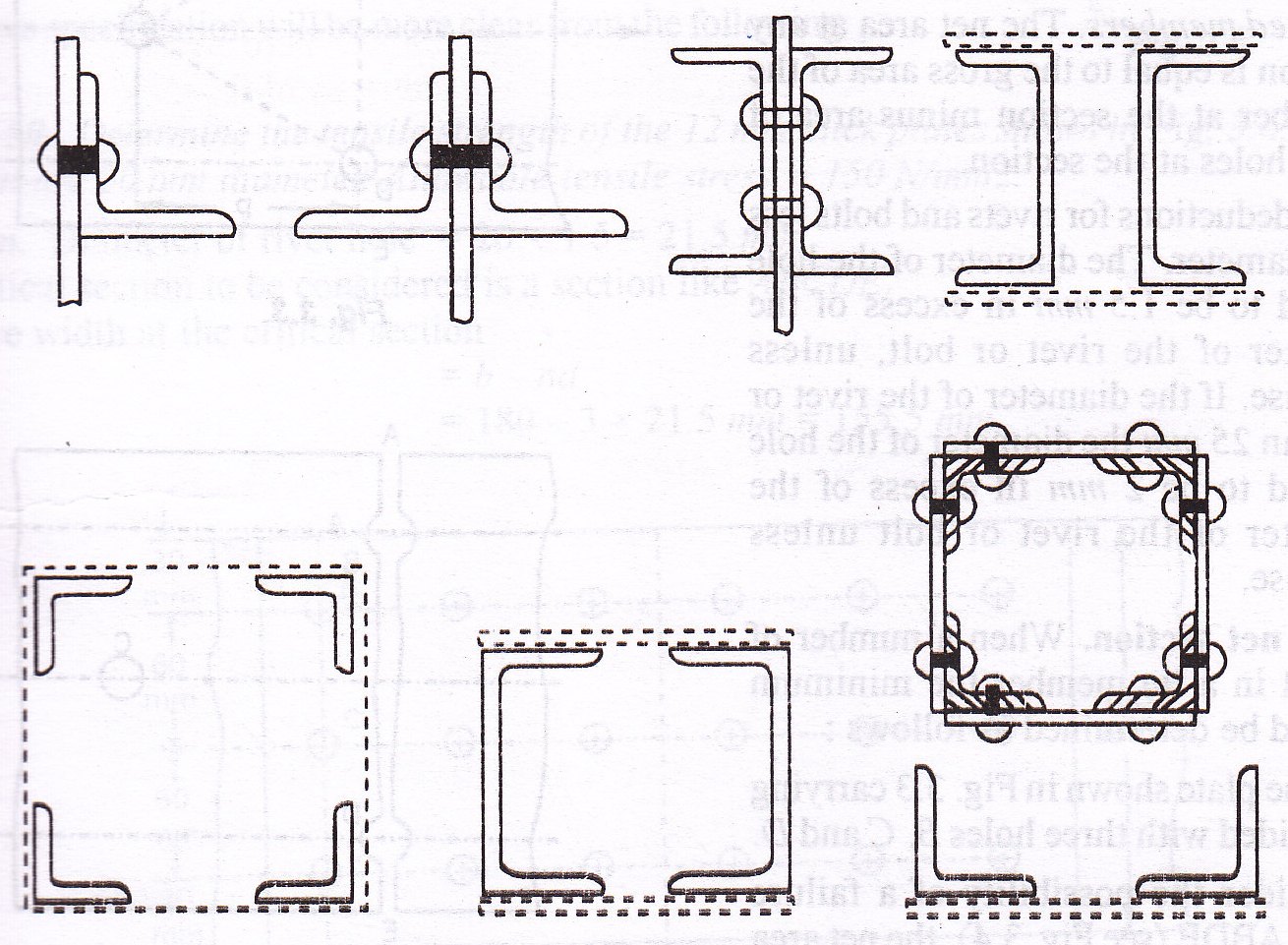
Besides the above two angle members, four angle members with or without a plate; two channel members may be used as tension members in more heavily loaded bridge trusses. The major types of tension members are shown in Fig. 8.2.
8.4 PERMISSIBLE TENSILE STRESS
For a tension member, it is necessary that the intensity of tensile stress on the net section of the member shall be less than the permissible limit. The I.S. specification has recommended the following permissible stresses.
The permissible stress in axial tension on the net effective area of the section shall not exceed 0.6 fy, where fy is the minimum yield stress of steel.
For example, if fy=250 N/mm2, Safe stress in axial tension = 0.6 x 250 = 150 N/mm2.
8.5 NET SECTIONAL AREA
The maximum stress for a tension member occurs at the section where the area is a minimum. The net area for tension members should be determined as follows:
Threaded rods: The sectional area at the root of the threads is regarded of the net area.
Riveted members: The net area at any section is equal to the gross area of the member at the section minus area of rivet holes at the section.
In making deduction for rivets and bolts less than 25 mm in diameter, the diameter of the hole shall be assumed to be 1.5 mm in excess of the nominal diameter of the rivet or bolt, unless specified otherwise. If the diameter of the rivet or bolt is greater than 25 mm the diameter of the hole shall be assumed to be 2 mm in excess of the nominal diameter of the rivet or bolt unless specified otherwise.
Minimum net section: When a number of holes are present in a tie member the minimum net section should be determined as follows:
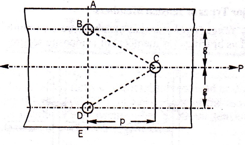
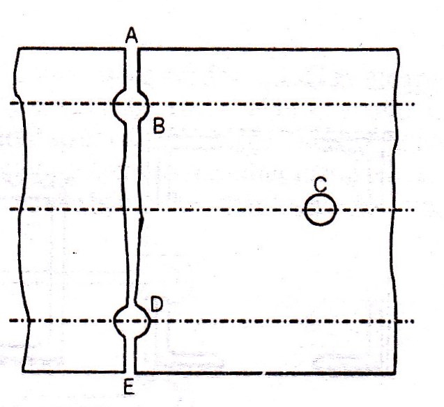
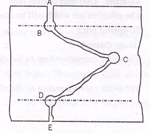
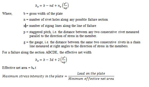
Consider the plate shown in Fig 8.3 carrying a pull P and provided with three holes, B, C and D. If we consider the possibility of a failure along the section ABDE (Fig. 8.4), the net area at the section equals the gross area of the plate minus area of two rivet holes. There may be possibility of a failure along the section ABCDE (Fig. 8.5). This can occur when the staggered pitch p is within a certain limit. For a case like this the net effective width be can be determined by the following rule:
8.6 NET EFFECTIVE SECTION FOR ANGLES AND TEES IN TENSION
The I.S 800 specification has stated the following in connection with the determination of the net effective section for angles and tees in tension.
a. Singles angles:
In the case of single angles in tension connected by one leg only (Fig. 8.6),
The net effective section of the angle = A1 + A2K
Where, A1 = Effective cross sectional area of the connected leg,
A2 = The gross-sectional area of the unconnected leg, and
![]()
b. Double angles back to back (and single tees)
When only one leg of each angle is connected to the same side of a gusset (or when the flange of the tee is connected to the gusset) as shown in Fig. 8.7,
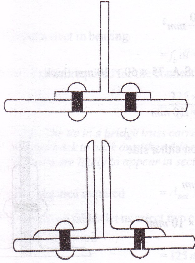
The net effective section = = A1 + A2K
Where, A1 = Effective cross sectional area of the connected leg,
A2 = The gross-sectional area of the unconnected leg, and
The angles shall be connected together along their lengths with tacking or stitch rivets at a spacing not exceeding 32 times the thickness or 300 mm whichever is less.
-
When the double angles are connected to each side of a gusset, the area to be taken in computing the mean tensile stress shall be the full gross area minus the area of rivet holes. The angles shall also be connected together along their lengths with tacking rivets.
-
When the double angles are not tack riveted each angle shall be designed as a single angle connected through one leg only.
The area of the leg of an angle shall be taken as the product of the thickness and the length from the outer corner minus half the thickness and the area of the leg of a tee as the product of the thickness and the depth minus the thickness of the flange.
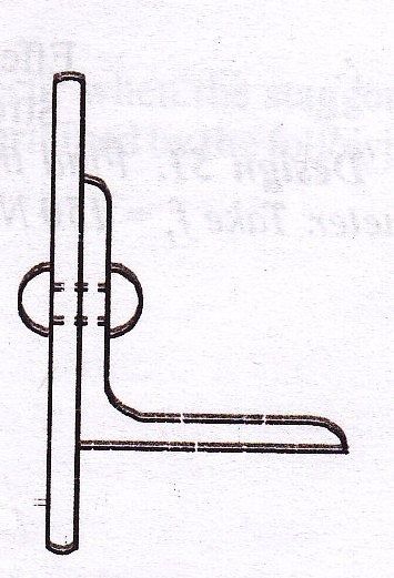
8.7 LUG ANGLES
To accommodate the necessary number of rivets for the connection of a member to a gusset plate a certain length of the member is utilized. When the load in the member is large many rivets may be required for the connection and the length of the member utilized for the connection itself may be large and may involve a considerable length of gusset plate. By using lug angles the length of the connection can be decreased.
Fig 8.8 shows a lug angle used for the connection of an angle member to the gusset plate. Similarly for the connection of a channel member two lug angles may be used as shown in Fig. 8.9.
In the case of angle members, the lug angles and their connections to the gusset or other supporting member shall be capable of developing a strength not less than 20 per cent in excess of the force in the outstanding leg of the angle and the attachment of the lug angles to the angle member shall be capable of developing 40 per cent in excess of that force.
Lug angles connecting a channel shaped member shall, as for as possible, be deposed symmetrically with respect to the section of the member. The lug angles and their connection to the gusset or other supporting member shall be capable of developing a strength of not less than 10 per cent in excess of the force not accounted for by the direct connection of the member and the attachment of the lug angles to the member shall be capable of developing 20 per cent in excess of that force.
In no case shall less than two bolts or rivets be used for attaching the lug angle to the gusset or other supporting member.
Last modified: Saturday, 5 October 2013, 7:34 AM