Site pages
Current course
Participants
General
MODULE 1.
MODULE 2.
MODULE 3.
MODULE 4.
MODULE 5.
MODULE 6.
MODULE 7.
MODULE 8.
MODULE 9.
MODULE 10.
MODULE 11.
MODULE 12.
LESSON 9. Design of Tension Member
9.1 INTRODUCTION
When a tension member is subjected to axial tensile force, then the distribution of stress over the cross-section is uniform. The complete net area of a member is effectively used at the maximum permissible uniform stress. Therefore, a tensile member subjected to axial tensile force is used to be efficient and economical member. The procedure of the design of a tension member is explained below with help of example problems.
9.2 STEPS TO BE FOLLOWED IN THE DESIGN OF A TENSION MEMBER
The following steps may be followed in the design of axially loaded tension members.
-
Corresponding to the loading on the structure of which the tension member is a part, the tensile force in the member is first computed.
-
The net area required for the member is determined by dividing the tensile force in the member by the permissible tensile stress.
-
Now, a suitable section having gross area about 20 per cent to 25 per cent greater than the estimated area is selected. For the member selected deductions are made for the area of rivet holes and the net effective area of the section is determined. If the net area of the section of the member so determined is greater than the net area requirement estimated in step i, the design is considered safe.
-
The slenderness ratio of a tension member shall not exceed 400. In the case of a tension member liable to reversal of stress due to the action of wind or earthquake, slenderness ratio shall not exceed 350. If the reversal of stress is due to loads others than wind or earthquake, the slenderness ratio shall not exceed 180.
Example 9.1: Determine the tensile strength of the 12 mm thick plate shown in Fig 9.1. Rivets used for the connection are 20 mm diameter. Allowable tensile stress is 150 N/mm2.
Solution
Diameter of the rivet hole = 20 + 1.5 = 21.5 mm
The critical section to be considered is a section like ABCDE.
Effective width at critical section = b – nd = 180 – (3 x 21.5) = 115.5 mm
Effective net area = 115.5 x 12 mm2 = 1386 mm2
Strength of plate = 1386 x 150 = 207900 N = 207.9 kN.
Example 9.2: Find the strength of the 12 mm thick plate shown in Fig. 9.2. All the holes are 21.5 mm as gross diameter. Take ft=150 N/mm2.

Solution
Gross diameter of rivet hole = 21.5 mm
The effective net width will be computed along the various chain lines
Staggered pitch p = 40 mm
Gauge distance g = 50 mm
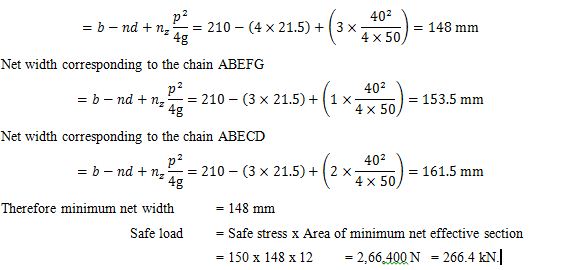
Net width corresponding to the chain ABCD = 210 – (2 x 21.5) = 167 mm
Net width corresponding to the chain ABECFG
Example 9.3: The tension member of a roof truss consist of two unequal angles 70 x 45 x 8 with the longer legs connected by 16 mm diameter rivets. Find the safe tension for the member, the angles being one on either side of the gusset plate.
Solution
Gross area of 2 angles, 70 x 45 x 8 = 1,712 mm2
Area of 2 rivet holes 2 x (16 + 1.5) x 8 = 280 mm2
Net area of the member 1712 – 280 = 1,432 mm2
Therefore safe tension for the member = 150 x 1432 = 2,14,800 N = 214.8 kN.
Example 9.4: The tension member of a roof truss carries a maximum axial tension of 250 kN. Design the section. Diameter of connecting rivets = 20 mm. Safe stress in tension = 150 N/mm2.
Solution
![]()
Referring to steel tables, let us choose two angles of I.S.A. 75 x 50 x 10 mm thick.
Gross area = 75 mm x 50 mm x 10 mm = 2,300 mm2.
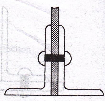
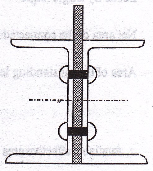
Let us assume that the angles are placed back to back on either side of the gusset plate (Fig. 9.3) with two rivets.
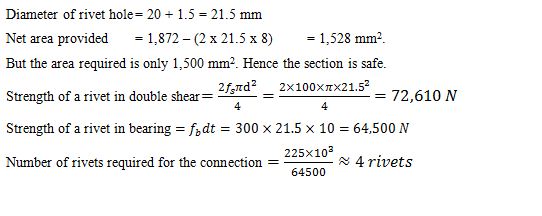
Diameter of rivet hole = 20 + 1.5 = 21.5 mm
Net area provided = 2,300 – (2 x 21.5 x 10) = 1,870 mm2.
But the area required is only 1,667 mm2. Hence the section is safe.
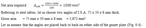
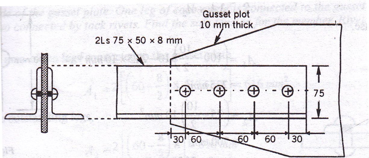
Example 9.5: The tie of a truss carries an axial tension of 225 kN. Design the section of the member and also the connection of the member to 10 mm thick gusset plate. Use 20 mm diameter rivets.
Solution
Example 9.6: The tie in a bridge truss carries an axial tension of 350 kN. The member is to consist of two channels connected back to back on either side of a gusset plate. The diameter of rivets used for the connection is 16 mm. Two rivets are likely to appear in section. Design the member. Safe stress in tension is 150 N/mm2.
Solution
Net area required
Referring to steel tables, let us select two channels ISLC, 125 (Fig. 9.5)
Dimensions of section = 125 mm x 65 mm
tf = 6.6 mm
tw = 4.4 mm
Gross area Ag = 1,367 mm2 per channel
Diameter of rivet hole = 16 + 1.5 = 17.5 mm
Making allowance for four rive holes,
Net area provided = 2 x 1367 – (4 x 17.5 x 4.4) = 2,426 mm2.
But the required area is only 2,333 mm2. Therefore, the section selected is safe.
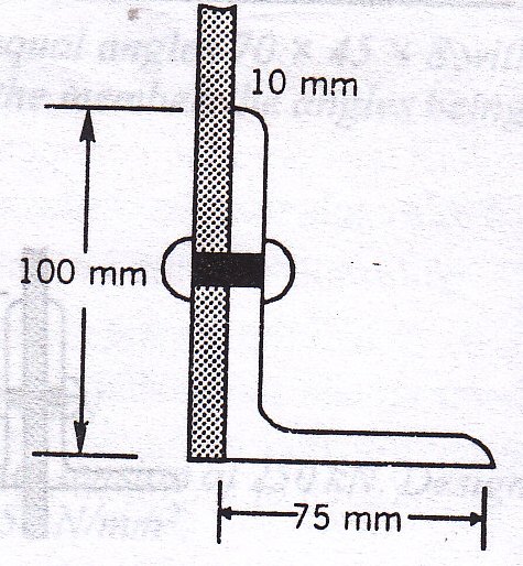
Example 9.7: The tension member of a roof truss consist of a single ISA 100 x 75 x 10 mm thick, connected at the end to a gusset plate with the longer leg vertical with 20 mm diameter rivet. Find the safe tension the member can withstand. Permissible tensile stress may be taken as 150 N/mm2.
Solution
Diameter of rivet hole = 20 + 1.5 = 21.5 mm
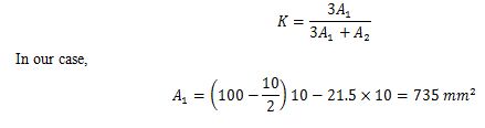
Net effective area provided
Where, A1 = Net sectional area of the connected leg,
A2 = Area of the unconnected leg, and
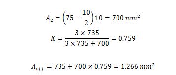
Safe axial tension = Aeff x Safe stress
= 1,266 x 150 = 1,89,900 N = 189.9 kN.
The tension member is shown in Fig. 9.6.
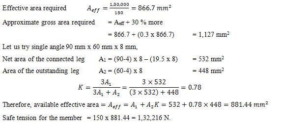
Example 9.8: Design a single angle tension member to sustain a tension of 1,30,000 N. Use 18 mm diameter rivets.
Solution
The single angle tension member is shown in Fig. 9.7.
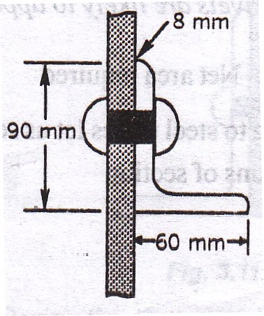
But actual tension in the member is only 1,30,000 N. Hence the design is safe.
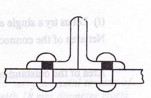
Example 9.9: A tension member consist of two angles 60 x 60 x 8 the angles being placed back to back on the same side of the gusset plate. One leg of each angle is connected to the gusset plate. The outstanding legs are also connected by tack rivets. Find the safe tension for the member. Rivets are 16 mm in diameter.
Solution
The tension member is shown in Fig. 9.8.
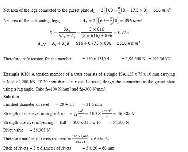
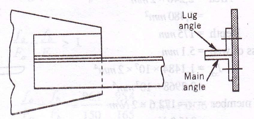
This being large the length of the connection can be decreased by using a lug angle,
Let the longer leg be the connected leg,
Area of the connected leg = (125-5)10 = 1,200 mm2
Area of the outstanding leg = (75-5)10 = 700 mm2
Therefore load taken by the connected leg
Therefore load taken by the outstanding leg = 200 – 126.3 = 73.7 kN
Connection to the gusset plate using a lug angle is shown in Fig. 9.9.
The lug angle should have a strength equal to 20 % greater than the strength of the outstanding leg.
Therefore strength required for the lug angle = 1.2 x 73.7 kN = 88.44 kN
Ne area required for the lug angle = (88.44 x 1000/150) = 589.6 mm2
Let us try 1 lug angle 125 x 75 x 6 mm
Gross area = 1,166 mm2
Net area = gross area – area of one rivet hole = 1,166 – (21.5 x 6) = 1,037 mm2
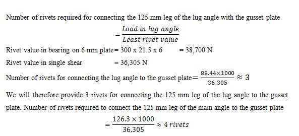
Strength required for connection between lug angle and the main angle is equal to 1.4 times the strength of the outstanding leg.
Therefore, strength required for this connection = 1.4 x 73.7 = 103.18 kN
Number of rivets required = (103.18 x 1000/36,305) ≈ 3
Last modified: Saturday, 5 October 2013, 7:35 AM