Site pages
Current course
Participants
General
MODULE 1.
MODULE 2.
MODULE 3.
MODULE 4.
MODULE 5.
MODULE 6.
MODULE 7.
MODULE 8.
MODULE 9.
MODULE 10.
MODULE 11.
MODULE 12.
LESSON 10. Design of Columns
10.1 INTRODUCTION
A column is defined as a structural member subjected to compressive force in a direction parallel to its longitudinal axis. The term stanchions and posts are also used for columns. In truss bridge girders, end compression members are termed as end posts. Columns are commonly classified as short and long columns. This classification is arbitrary and there is no absolute way to determine the exact limits for each classification.
10.2 AXIALLY LOADED COLUMNS
In an axially loaded column, the load is applied at the centroid of the section and in a direction parallel to the longitudinal axis of the column. The terms centrally loaded and concentrically loaded are also used for axially loaded columns. An axially loaded column as defined by the structural engineers transmits a compressive force without an explicit design requirement to carry lateral loads or end moments.
An ideal column is assumed initially to be perfectly straight and is centrally loaded. Consider a case of a slender ideal column. The column is vertically fixed at the base and free at the upper end and subjected o an axial load P as shown in Fig. 10.1. The column is assumed to be perfectly elastic. When the value of load P is less than critical load and stress is within the limit of proportionality, the column remains straight. The column is in stable equilibrium. If a small lateral load is applied at the free end, the column defect. On withdrawal of the lateral load, the column resumes its vertical position and deflection vanishes. When the axial load P gradually increased, a stage will be reached when the vertical position of the column is in the unstable equilibrium. If a small lateral load is applied, a deflection will be produced, which will not vanish on withdrawal of lateral load.
The axial load which is sufficient to keep the column in such a slight deflected shape is called critical load. Critical load is also called a buckling load or crippling load. The buckling load is defined as the load at which a member or a structure as a whole collapses in service (or buckles in load test). The buckling is defined as the sudden bending, warping, curling or crumbling of the elements or members under compressive stresses. The direction of buckling of a column depends upon flexural rigidity EI, of the column. It buckles in a direction perpendicular to the axis about which the moment of inertia of the section is minimum.
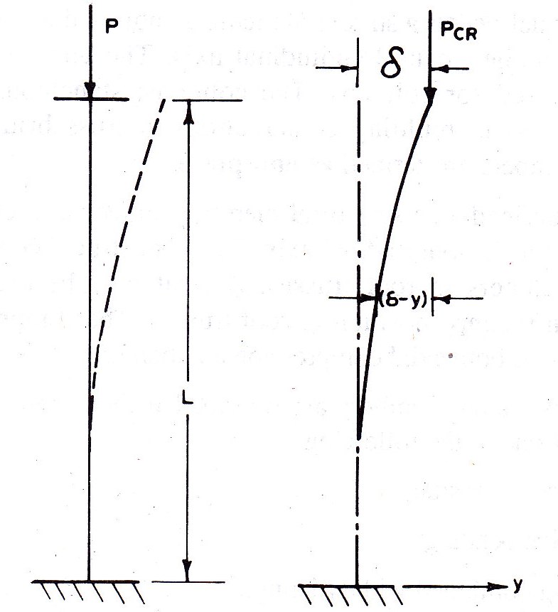
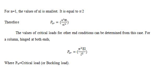
In about 1759, a Swiss mathematician Prof. Leonhard Euler derived the most popular column formula. The critical load for the column as shown in Fig 10.1 was determined as follows.
The differential equation of the deflected shape of the column is
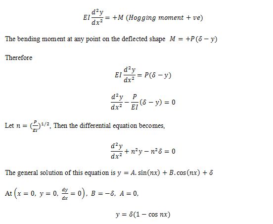
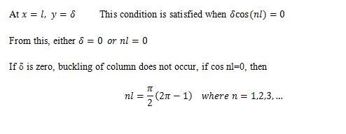
Since each half of the column is in the same position as the whole of the column. This is called fundamental case of buckling of a bar.
10.3 EFFECTIVE LENGTH OF COMPRESSION MEMBER
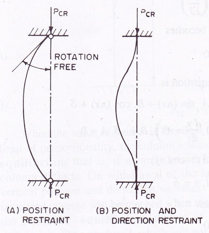
The effective length of a compression member depends upon end restraint conditions. The end restraint conditions are of two types as given below:
Position restraint
Direction restraint
10.3.1 Position restraint
In position restraint, end of the column is not free to change its position but rotation about the end of the column can take place e.g., hinged end of column as shown in Fig. 10.2.A
10.3.2 Direction restraint
In direction restraint, end of the column is free to change its position but rotation about the end of the column cannot take place.
When an end of a column is having restraint in position and direction both, then end is not free to change its position and the rotation about the end of the column also cannot take place as shown in Fig. 10.2.B
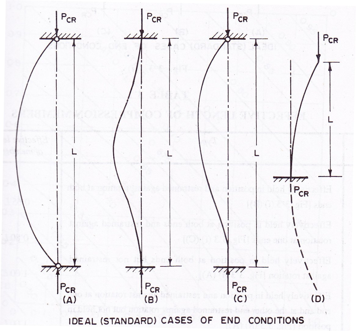
There are various possible combinations of restraints about either or both axes. The restraint conditions at the two ends of a column may be different or may be same. Following are the ideal cases of the end conditions:
Both ends of column hinged
Both ends of column fixed
One end of column fixed and the other end hinged
One end of column fixed and the other end free.
The deflected shapes of columns under critical loads have been shown in Fig. 10.3. A, B, C and D respectively. The actual lengths have been indicated by ‘L’. Case one, both ends of the column hinged have been considered as standard case. The effective length (l) of a column is expressed in terms of equivalent length of compression members, hinged at both ends. It is the length of column between two adjacent points of zero moments and is represented by ‘l’. It is also called as unsupported length.
The ideal end conditions cannot be achieved in actual practice. The effective length of a compression member is adopted as per Table 10.1 as recommended by BIS in IS:800-1984 for different types of compression members. The effective length as given in this table will be adequate in most of the cases and the same may also be adopted where the column directly form part of the frame structures.
Table 10.1 EFFECTIVE LENGTH OF COMPRESSION MEMBERS
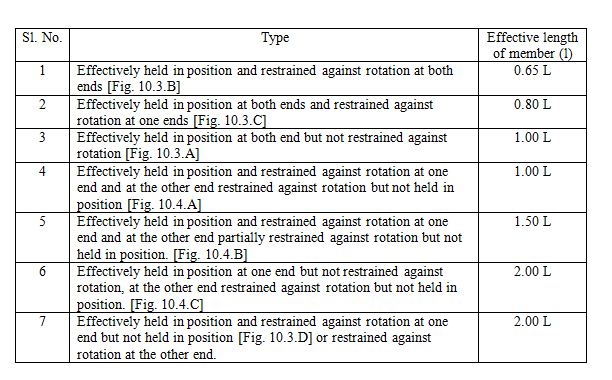
Note: For battened struts, the effective length l is increased by 10 per cent.
Where the exact frame analysis is not done, the effective length of columns in the frame structures may be found from the ratio of effective length to the unsupported length (l/L) from Fig. 10.5 when the relative displacements of the column is prevented (i.e. when there is no sway) and from Fig. 10.6 when the relative lateral displacement of the ends is not prevented (i.e. without restraint against sway viz., the sway occurs), when sway occurs, IS:800-1984 recommends that the effective length ratio, (l/L) may not be taken to be less than 1.2.
In Fig. 10.5 and Fig. 10.6,
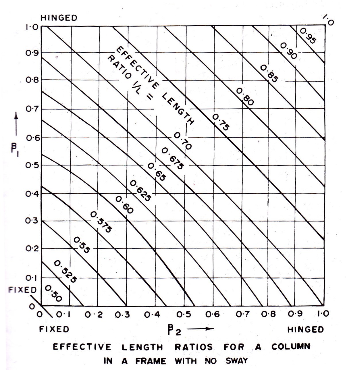
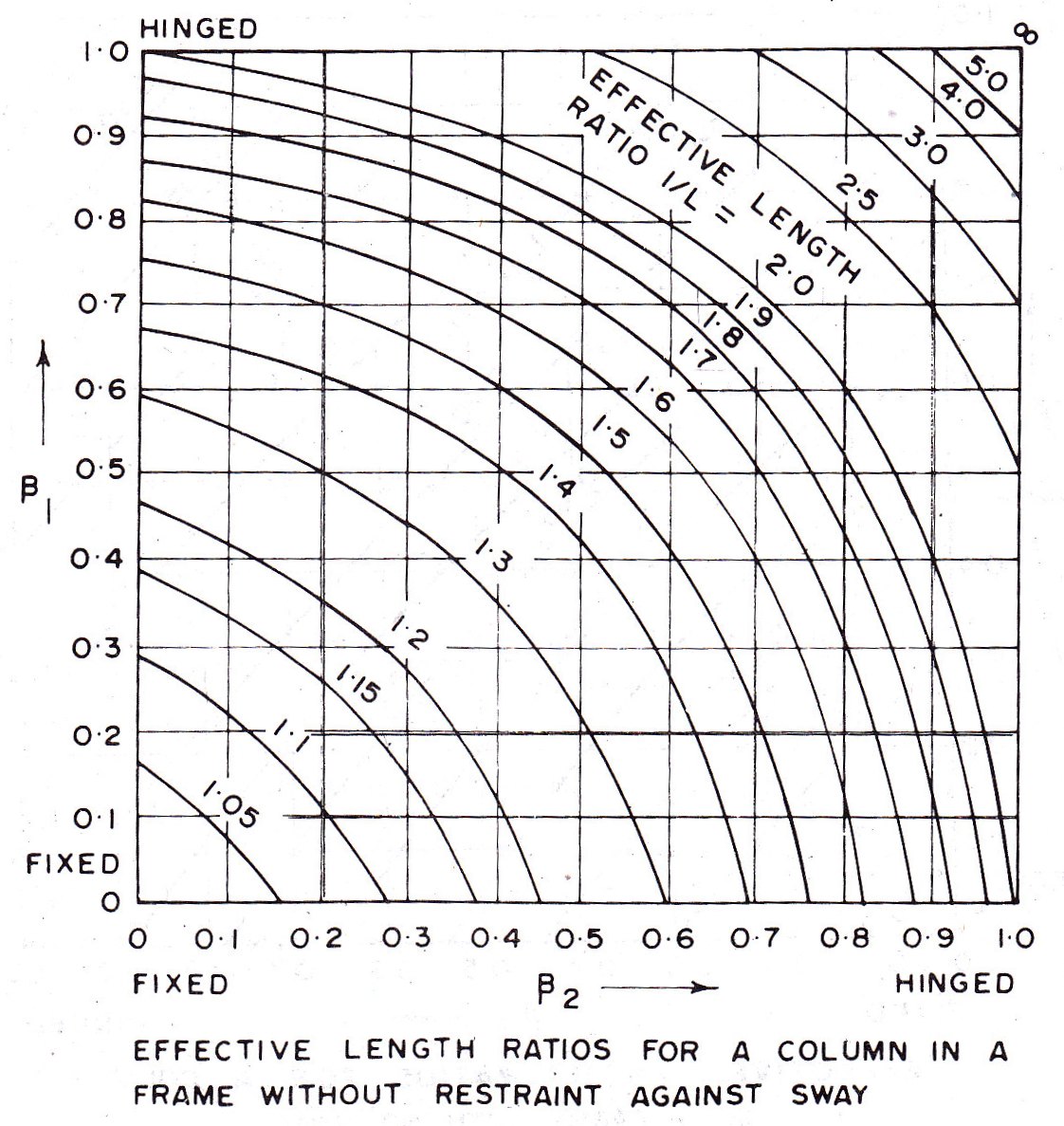
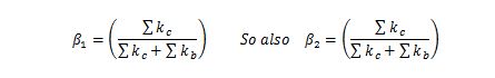
Where, the summation is to be done for the members framing into a joint at top and bottom respectively, and
kc = flexural stiffness of the column and
kb = flexural stiffness of the beam
Fig. 10.5 and Fig. 10.6 are from the paper titled as Effective lengths of columns in multistory buildings by Professor R.H.Wood, published in the structural Engineer Vol. 52, No. 7 July 1974. It is worthwhile to note that IS;800-1984 ‘code of practice for general construction in steel’ and IS:456-1978 ‘code of practice for plain and reinforced concrete’ have recommended the same effective lengths for the columns with similar support conditions.
10.4 EFFECTIVE SECTIONAL AREA
The gross cross-sectional area is the area as calculated from the specified size of the member or part thereof. The effective sectional area of a compression member is the gross cross-sectional area of the member. The deduction is not made for members connected by rivets, bolts and pins. If the holes are not filled by the fastening material, then deduction is made for unfilled holes. The effective area is however modified when the ratio of the outstand to thickness exceeds the limits specified by BIS. The deduction is also made from the gross cross-sectional area for excessive effective plate width (if any) to determine the effective sectional area.
10.5 RADIUS OF GYRATION
The radius of gyration of a section is a geometrical property of the section and it is denoted by r
r = (I/A)1/2
where I=moment of inertia of the section about the axis.
r=radius of gyration of the section about the axis
A=effective sectional area of the section.
10.6 SLENDERNESS RATIO OF COMPRESSION MEMBER
The slenderness ratio of a compression member is defined as ratio of effective length of compression member (l) to appropriate radius of gyration (r)
Slenderness ratio, λ=l/r
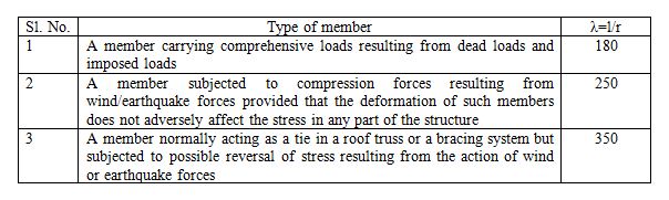
The radii of gyration about various axes of rolled steel sections can be obtained from structural steel section tables (ISI Handbook No.1). The minimum radius of gyration is used for computing the maximum slenderness ratio. For built-up compression members, value of radius of gyration is calculated. The slenderness ratio for a compression member should be as small as possible so that the material may be stressed to its greatest possible limit. The maximum slenderness ratio of compression members should not exceed the value given in Table 10.2. These limits have been laid down by BIS in IS:800-1984.
The end restraints of columns are often different in the two principal planes. The different moments of inertia of the column cross-section in these planes are sometimes desirable to achieve approximately equal slenderness ratios. The intermediate supports are provided to the columns for this purpose.
Table 10.2 MAXIMUM SLENDERNESS RATIO OF COMPRESSION MEMBER (λ=l/r)
The intermediate supports reduce the unsupported length of the columns. When the unsupported lengths of columns are reduced then the smaller sections may be used at a higher average stress. Sometimes, the intermediate supports are furnished only in one direction, for example, a rolled steel I-section column is having its continuous length up to two storeys. At the level of one storey, intermediate support is provided by connecting beams with the web. The radius of gyration, ryy of the section, about yy-axis (axis parallel to the web) is much smaller than the radius of gyration rxx of the section, about xx-axis.
By providing the intermediate support, the effective length of the column become different in two different directions. The effective length of column, lyy for bending about yy-axis is found by considering the length of column between one-storey only. The effective length of column lxx for bending about xx-axis is found by considering the length of column between two storeys. It is seen that the effective length of column lyy is much smaller than that of lxx. The values of slenderness ratio (lyy/ryy) and (lxx/rxx) about two directions may be made approximately equal. As such the use of sections with different values of radii of gyration in two directions may be made economical. When a column is subjected to different bending moments in two directions then, the greater value of r may be kept in the direction of greater moment. The intermediate supports in the weak direction make the use of I-section and channel section economical.
10.7 COLUMN FORMULAE FOR AXIAL STRESS IN COMPRESSION
The strength of a column depends upon large number of variables. The efforts are made to obtain a design formula by fitting a curve to experimentally found buckling loads for the intermediate range of the slenderness ratio. It is tried to draw a curve which may merge with the Euler hyperbola in the very slender column range on one side and with the material yield strength for the zero length on the other side.
A perfectly straight column of perfectly homogeneous material (i.e. an ideal column) is subjected to an axial load. The primary object is to find the average axial stress in compression, which corresponds to the allowable load. The average axial stress is uniform across the section. It is given by
σac =(Pa/A)
Where Pa = allowable load and A = cross-sectional area of the column
The required cross-sectional area for a given design load may be found conveniently in case σc is known
Areqd = (P/σc)
Where P is the design load
10.8 DESIGN OF AXIALLY LOADED COMPRESSION MEMBER
When a column or compression member is designed, for given load, actual length of the member and its support conditions, the cross-sectional shape of the member is determined. The cross-sectional shape of axially loaded compression member depends largely on whether the compression member is long or short and whether it carries a small load or a large load. It is difficult to decide, whether a column is short or long. It is arbitrarily decided.
When the slenderness ratio of a column is less than 60, it may be considered as a short column. When the slenderness ratio is between 60 and 180, the column may be considered as long column. Following are the length and load categories arbitrarily made for design of compression members:
- Short compression members with small loads
- Short compression members with large loads
- Long compression members with small loads
- Long compression members with intermediate load.
The strength of axially loaded compression member depends upon slenderness ratio (l/rmin). For the design of axially loaded compression member load to be carried, the length of compression member and end conditions are known. The effective length of the compression member for the given end conditions is computed. The radius of gyration of compression member is not known as the cross-sectional shape of the compression member is not known. The allowable working stress in compression can be found when the slenderness ratio is known. There is no direct method of designing a compression member. The compression member is designed by trial and error method. The design of compression member is also done by using safe load tables, if available.
ISI handbook No.1 provides tables for safe concentric loads on rolled steel column sections (HB-sections) for bending about xx-axis and yy-axis. The effective length of column is determined knowing the end conditions. The values of safe concentric loads corresponding to respective effective lengths are given for various sizes of HB-sections. A column section having safe axial load equal to or slightly greater than the required load on the column is selected.
Design procedure: Following are the usual steps in design of compression members.
Step 1. The slenderness ratio for the compression member and the value of yield stress for the steel are assumed. For the rolled steel beam section compression members, the slenderness ratio varies from 70 to 90. For struts, the slenderness ratio varies from 110 to 130. For compression members carrying large loads, the slenderness ratio is about 40.
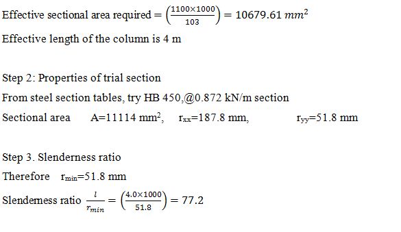
Step 2. The effective sectional area (A) required for compression member is determined.
A = (P/σc), Where P is the design load to be carried by the member
Step 3. From the steel section tables, section for the compression member of the required area is selected. The section for the compression member is selected such that it has the largest possible radius of gyration for the required sectional area. It should also be most economical section.
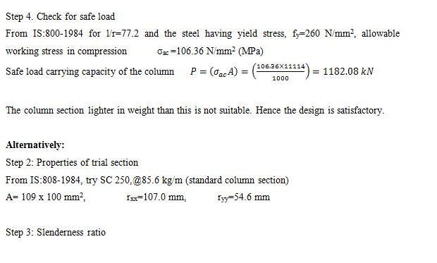
Step 4. Knowing the geometrical properties of the section slenderness ratio is computed and allowable axial stress in compression is found from IS:800-1984 for the quality of steel assumed.
Step 5. The safe load carrying capacity of the compression member is determined.
The section selected for the compression member is revised in case the safe load carrying of the compression member is less than or much larger than the load to be carried by it.
Example 10.1 A rolled steel beam section HB 350 @0.674 kN/m is used as a stanchion. If the unsupported length of the stanchion is 4 m, determine safe load carrying capacity of the section.
Solution:
Step 1: Properties of I-section
HB 350 @ 0.674 kN/m section is used as a stanchion. From the steel tables, the geometrical properties of the section are as follows:
Sectional area A = 8591 mm2
Radius of gyration rxx= 149.3 mm
Radius of gyration ryy= 53.4 mm
Step 2: Slenderness ratio
Minimum radius of gyration rmin= 53.4 mm
Unsupported length l= 4 m

Step 1: Properties of I-section
From IS:808-1964, the geometrical properties of the section are as follows:
Sectional area A = 109 x 102 mm2
Radius of gyration rxx= 107 mm
Radius of gyration ryy= 54.6 mm
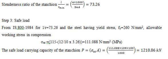
Step 2: Slenderness ratio
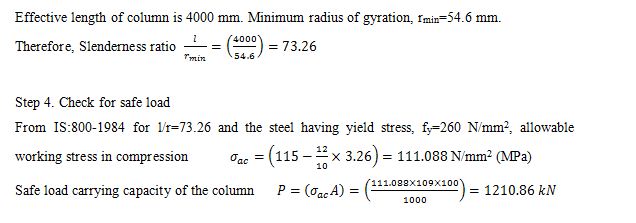
Minimum radius of gyration rmin= 54.6 mm
Unsupported length l= 4 m = 4000 mm
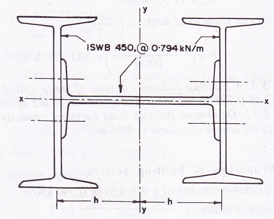
Example 10.3 A built-up column consist of three rolled steel beam sections WB 450 @0.794 kN/m, connected effectively to act as one column as shown in Fig. 10.7. Determine the safe load carrying capacity of built-up section, if unsupport length of column is 4.25 m.
Solution:
Step 1: Properties of built-up section
The built-up column consist of 3 WB 450 @0.794 kN/m
From steel section tables, area of section =(3 x 101.15 x 100) = 30345 mm2
Moment of inertia of built-up section about xx-axis
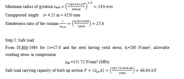
Ixx=[2 x 35057.6 + 1706.7] x 104 = 71821 x 104 mm4
Moment of inertia of built-up section about yy-axis
Iyy=[35057.6 x 104 + 2 x 1706.7 x 104 + 2Ah2] = 38471 x 104 + 2Ah2 mm4
Where A=sectional area of one I-section
Iyy=[38471.0 + 2 x 101.15(22.5 + ½ x0.92)2 ] x 104 mm4
= 145115.79 x 104 mm4
Step 2: Slenderness ratio
Ixx is less than Iyy. Therefore rxx is Minimum.
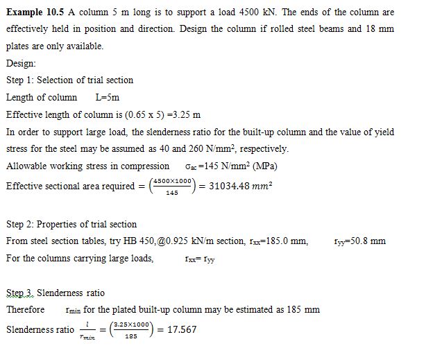
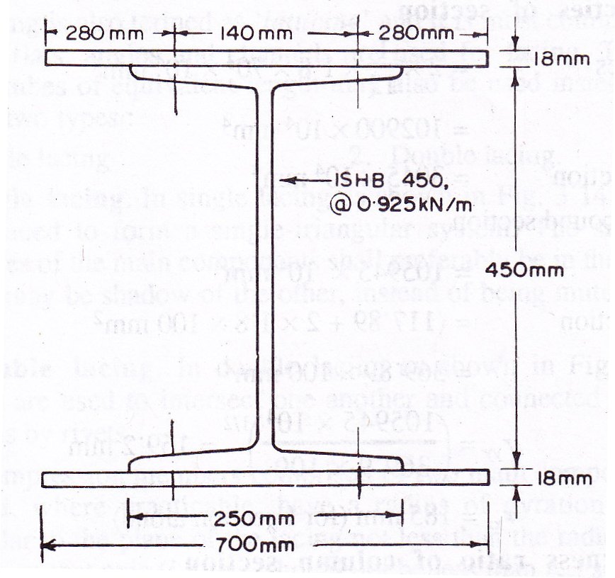
Example 10.4 Design a rolled steel beam section column to carry an axial load 1100 kN. The column is 4 m long and adequately restrained in position but not in direction at both ends:
Design: The slenderness ratio for the column and the value of yield stress for the steel to be used may be assumed as 80 and 260 N/mm2 respectively.
Step 1. Selection of trial section
Allowable stress as per IS:800-1984, σac =103 N/mm2
Step 4. Area of plates
From IS:800-1984 for l/r=17.567 and the steel having yield stress, fy=260 N/mm2, allowable working stress in compression σac =154.486 N/mm2 (MPa)
![]()
Area of HB 450,@0.925 kN/m is 11789 mm2
Area to be provided by two cover plates = 17339.74 mm2
Area to be provided by one plate = 8669.87 mm2
Plates available = 18 mm
Width required = (8669.87/18) =481.66 mm
Provide 700 mm width of cover plate
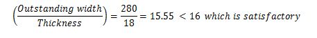
Step 5: Check for outstanding width; thickness ratio for cover plate
Outstanding width = ½ (700-140)=560/2=280 mm
Thickness = 18 mm
Step 6: Check for load carrying capacity
- Properties of section
Iyy of plates = 2 x (1/12) x 1.8 x 703 x 104 mm4 = 102900 x 104 mm4
Iyy of H-section = 3045 x 104 mm4
Iyy of compound section = 105945 x 104 mm4
Area of section = (117.89 + 2 x 1.8 x 100 mm2 = 369.89 x 100 mm2
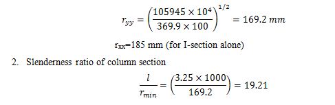
From IS:800-1984 for l/r=19.21 and the steel having yield stress, fy=260 N/mm2, allowable working stress in compression σac =154.158 N/mm2 (MPa)
![]()
Hence, the design is satisfactory. Provide HB 450,@0.925 kN/m with two plates 700 mm x 18 mm. One plate is connected with each flange of I-section. The design drawing is given in Fig. 10.8
Step 4. Area of plates
From IS:800-1984 for l/r=17.567 and the steel having yield stress, fy=260 N/mm2, allowable working stress in compression σac =154.486 N/mm2 (MPa)
![]()
Area of HB 450,@0.925 kN/m is 11789 mm2
Area to be provided by two cover plates = 17339.74 mm2
Area to be provided by one plate = 8669.87 mm2
Plates available = 18 mm
Width required = (8669.87/18) =481.66 mm
Provide 700 mm width of cover plate
Step 5: Check for outstanding width; thickness ratio for cover plate
Outstanding width = ½ (700-140)=560/2=280 mm
Thickness = 18 mm
![]()
Step 6: Check for load carrying capacity
- Properties of section
Iyy of plates = 2 x (1/12) x 1.8 x 703 x 104 mm4 = 102900 x 104 mm4
Iyy of H-section = 3045 x 104 mm4
Iyy of compound section = 105945 x 104 mm4
Area of section =(117.89 + 2 x 1.8 x 100 mm2 = 369.89 x 100 mm2
Last modified: Saturday, 5 October 2013, 7:37 AM