Site pages
Current course
Participants
General
MODULE 1.
MODULE 2.
MODULE 3.
MODULE 4.
MODULE 5.
MODULE 6.
MODULE 7.
MODULE 8.
MODULE 9.
MODULE 10.
MODULE 11.
MODULE 12.
LESSON 11. Design of Compression Members
11.1 INTRODUCTION
A strut is defined as a structural member subjected to compression in a direction parallel to its longitudinal axis. The term strut is commonly used for compression members in roof trusses. A strut may be used in a vertical position or in an inclined position in roof trusses. The compression members may be subjected to both axial compression and bending.
When compression members are overloaded then their failure may take place because of one of the following:
-
Direct compression
-
Excessive bending
-
Bending combined with twisting
The failure of column depends upon its slenderness ratio. The load required to cause above mentioned failures decreases as the length of compression member increases, the cross-sectional area of the member being constant.
11.2 COMMON SECTIONS OF COMPRESSION MEMBERS
The common sections used for compression members are shown in Fig. 11.1 with their approximate radii of gyration. A column or a compression member may be made of many different sections to support a given load. Few sections satisfy practical requirement in a given case. A tubular section is most efficient and economical for the column free to buckle in any direction. The radius of gyration r for the tubular section in all the directions remains same. The tubular section has high local buckling strength. The tubular sections are suitable for medium loads. However, it is difficult to have their end connections. A solid round bar having a cross-sectional area equal to that of a tubular section has radius of gyration, r much smaller than that of tube. The solid round bar is less economical than the tubular section. The solid round bar is better than the thin rectangular section or a flat strip. The radius of gyration of flat strip about its narrow direction is very small. Theoretically, the rods and bars do resist some compression. When the length of structural member is about 3 m, then the compressive strengths of the rods and bars are very small.
Single angle sections are rarely used except in light roof trusses, because of eccentricity at the end connections. Tee-sections are often used in roof trusses. The single rolled steel I-section and single rolled steel channel section are seldom used as column. The value of radius of gyration r, about the axis parallel to the web is small. The intermediate additional supports in the weak direction make the use of these sections economical. Sometimes the use of I-sections and channel sections are preferred because of the method of rolling at the mills, since, the out-to-out dimensions remain same for a given depth. This failure is not there with other rolled steel sections. The costs of single rolled steel sections per unit weight are less than those of built-up sections. Therefore the single rolled steel sections are preferred so long as their use is feasible.
11.3 STRENGTH OF COMPRESSION MEMBERS
The strength of a compression member is defined as its safe load carrying capacity. The strength of a centrally loaded straight steel column depends on the effective cross-sectional area, radius of gyration (viz., shape of the cross-section), the effective length, the magnitude and distribution of residual stresses, annealing, out of straightness and cold straightening. The effective cross-sectional area and the slenderness ratio of the compression members are the main features, which influence its strength. In case, the allowable stress is assumed to vary parabolically with the slenderness ratio, it may be proved that the efficiency of a shape of a compression member is related to A/r2. The efficiency of a shape is defined as the ratio of the allowable load for a given slenderness ratio to that for slenderness ratio equal to zero. The safe load carrying capacity of compression member of known sectional area may be determined as follows:
Step 1. From the actual length of the compression member and the support conditions of the member, which are known, the effective length of the member is computed.
Step 2. From the radius of gyration about various axes of the section given in section tables, the minimum radius of gyration (rmin) is taken. rmin for a built up section is calculated.
Step 3. The maximum slenderness ratio (l/ rmin) is determined for the compression member.
Step 4. The allowable working stress (σac) in the direction of compression is found corresponding to the maximum slenderness ratio of the column from IS:800-1984.
Step 5. The effective sectional area (A) of the member is noted from structural steel section tables. For the built up members it can be calculated.
Step 6. The safe load carrying capacity of the member is determined as P=(σac.A), where P=safe load
11.4 ANGLE STRUTS
The compression members consisting of single sections are of two types:
-
Discontinuous members
-
Continuous members
11.4.1 Continuous members
The compression members (consisting of single or double angles) which are continuous over a number of joints are known as continuous members. The top chord members of truss girders and principal rafters of roof trusses are continuous members. The effective length of such compression members is adopted between 0.7 and 1.0 times the distance between the centres of intersections, depending upon degree of restraint provided. When the members of trusses buckle in the plane perpendicular to the plane of the truss, the effective length shall be taken as 1.0 times the distance between the points of restraint. The working stresses for such compression members is adopted from IS:800-1984 corresponding to the slenderness ratio of the member and yield stress for steel.
11.4.2 Discontinuous members
The compression members which are not continuous over a number of joints, i.e., which extend between two adjacent joints only are known as discontinuous members. The discontinuous members may consist of single angle strut or double angle strut. When an angle strut is connected to a gusset plate or to any structural member by one leg, the load transmitted through the strut, is eccentric on the section of the strut. As a result of this, bending stress is developed along with direct stress. While designing or determining strength of an angle strut, the bending stress developed because of eccentricity of loading is accounted for as follows:
i.Single angle strut
When single angle discontinuous strut is connected to a gusset plate with one rivet as shown in Fig. 11.2.A, its effective length is adopted as centre to centre of intersection at each end and the allowable working stress corresponding to the slenderness ratio of the member is reduced to 80 per cent. However, the slenderness ratio of such single angle strut should not exceed 180.
When a single angle discontinuous strut is connected with two or more number of rivets or welding as shown in Fig. 11.2.B, its effective length is adopted as 0.85 times the length of strut centre to centre of intersection of each end and allowable working stress corresponding to the slenderness ratio of the member is not reduced.
ii.Double angle strut
-
A double angle discontinuous strut with angles placed back to back and connected to both sides of a gusset or any rolled steel section by not less than two rivets or bolts or in line along the angles at each end or by equivalent in welding as shown in Fig. 11.3.A, can be regarded as an axially loaded strut. Its effective length is adopted as 0.85 times the distance between intersections, depending on the degree of restraint provided and in the plane perpendicular to that of the gusset, the effective length ‘l’ shall be taken as equal to the distance between centres of the intersections. The tacking rivets should be provided at appropriate pitch.
-
The double angles, back to back connected to one side of a gusset plate or a section by one or more rivets or bolts or welds as show in Fig. 11.3.B, these are designed as single angle discontinuous strut connected by single rivet or bolt.
If the struts carry in addition to axial loads, loads which cause transverse bending, the combined bending and axial stress shall be checked as described for the columns subjected to eccentric loading. The tacking rivets should be provided at appropriate pitch.
The tacking rivets are also termed as stitching rivets. In case of compression members, when the maximum distance between centres of two adjacent rivets exceeds 12 t to 200 mm whichever is less, then tacking rivets are used. The tacking rivets are not subjected to calculated stress. The tacking rivets are provided throughout the length of a compression member composed of two components back to back. The two components of a member act together as one piece by providing tacking rivets at a pitch in line not exceeding 600 mm and such that minimum slenderness ratio of each member between the connections is not greater than 40 or 0.6 times the maximum slenderness ratio of the strut as a whole, whichever is less.
In case where plates are used, the tacking rivets are provided at a pitch in line not exceeding 32 times the thickness of outside plate or 300 mm whichever is less. Where the plates are exposed to weather the pitch in line shall not exceed 16 times the thickness of the outside plate or 200 mm whichever is less. In both cases, the lines of rivets shall not be apart at a distance greater than these pitches.
The single angle sections are used for the compression members for small trusses and bracing. The equal angle sections are more desirable usually. The unequal angle sections are also used. The minimum radius of gyration about one of the principal axis is adopted for calculating the slenderness ratios. The minimum radius of gyration of the single angle section is much less than the other sections of same cross-sectional area. Therefore, the single angle sections are not suitable for the compression member of long lengths. The single angle sections are commonly used in the single plane trusses (i.e., the trusses having gusset plates in one plane). The angle sections simplify the end connections.
The tee-sections are suitable for the compression members for small trusses. The tee-sections are more suitable for welding.
Example 11.1 A single angle discontinuous strut ISA 150 mm x 150 mm x 12 mm (ISA 150 150,@0.272 kN/m) with single riveted connection is 3.5 m long. Calculate safe load carrying capacity of the section.
Solution:
Step 1: Properties of angle section
ISA 150 mm x 150 mm x 12 mm (ISA 150 150,@0.272 kN/m) is used as discontinuous strut. From the steel tables, the geometrical properties of the section are as follows:
Sectional area A = 3459 mm2
Radius of gyration rxx= ryy=149.3 mm
Radius of gyration ruu= 58.3 mm, rvv=29.3 mm
Step 2: Slenderness ratio,
Minimum radius of gyration rmin= 29.3 mm
Effective length of strut l= 3.5 m
Slenderness ratio of the strut
Step 3: Safe load
From IS:800-1984 for l/r=119.5 and the steel having yield stress, fy=260 N/mm2, allowable working stress in compression σac =64.45 N/mm2 (MPa)
For single angle discontinuous strut with single riveted connection, allowable working stress
0.80 σac = (0.80 x 64.45) = 51.56 N/mm2.
The safe load carrying capacity ![]()
Example 11.2 In case in Example 11.1, a discontinuous strut 150 x 150 x 15 angle section is used, calculate the safe load carrying capacity of the section.
Solution:
Step 1: Properties of angle section
Angle section 150 mm x 150 mm x 15 mm is used as discontinuous strut. From the steel tables, the geometrical properties of the section are as follows:
Sectional area A = 4300 mm2
Radius of gyration rxx= ryy=45.7 mm
Radius of gyration ruu= 57.6 mm, rvv=29.3 mm
Step 2: Slenderness ratio,
Minimum radius of gyration rmin= 29.3 mm
Effective length of strut l= 3.5 m
Slenderness ratio of the strut ![]()
Step 3: Safe load
From IS:800-1984 for l/r=119.5 and the steel having yield stress, fy=260 N/mm2, allowable working stress in compression σac =64.45 N/mm2 (MPa)
For single angle discontinuous strut with single riveted connection, allowable working stress
0.80 σac = (0.80 x 64.45) = 51.56 N/mm2.
The safe load carrying capacity ![]()
Example 11.3 In Example 11.1, if single angle discontinuous strut is connected with more than two rivets in line along the angle at each end, calculate the safe load carrying capacity of the section.
Solution:
Step 1: Properties of angle section
Discontinuous strut ISA 150 mm x 150 mm x 12 mm (ISA 150 150,@0.272 kN/m) is used with double riveted connections. From the steel tables, the geometrical properties of the section are as follows:
Sectional area A = 3459 mm2
Radius of gyration rxx= ryy=149.3 mm
Radius of gyration ruu= 58.3 mm, rvv=29.3 mm
Length of strut between centre to centre of intersection L=3.50 m
Step 2: Slenderness ratio,
Minimum radius of gyration rmin= 29.3 mm
Effective length of discontinuous strut double riveted 0.85 x L= 0.85 x 3.5 = 2.975 m
Slenderness ratio of the strut ![]()
Step 3: Safe load
From IS:800-1984 for l/r=101.5 and the steel having yield stress, fy=260 N/mm2, allowable working stress in compression σac =71.65 N/mm2 (MPa)
Allowable working stress for discontinuous strut double riveted is not reduced.
The safe load carrying capacity ![]()
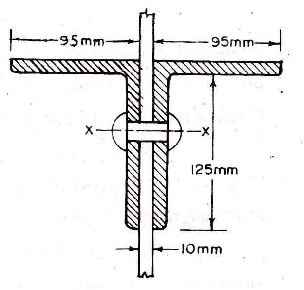
Example 11.4 A double angle discontinuous strut ISA 125 mm x 95 mm x 10 mm (ISA 125 95,@0.165 kN/m) long legs back to back is connected to both the sides of a gusset plate 10 mm thick with 2 rivets. The length of strut between centre to centre of intersections is 4 m. Determine the safe load carrying capacity of the section.
Solution:
Step 1: Properties of angle section
The double angle discontinuous strut 2 ISA 125 mm x 95 mm x 10 mm (ISA 125 95,@0.165 kN/m) is shown in Fig. 11.4. Assume the tacking rivets are used along the length. From the steel tables, the geometrical properties of (two angle back to back) the sections are as follows:
Sectional area A = 4204 mm2
Radius of gyration rxx= 39.4 mm
Angles are 10 mm apart
Radius of gyration ryy= 40.1 mm
Length of strut between centre to centre of intersection L=4 m
Step 2: Slenderness ratio,
Minimum radius of gyration rmin= 39.4 mm
Effective length of discontinuous strut 0.85 x L= 0.85 x 4.0 = 3.40 m
Slenderness ratio of the strut ![]()
Step 3: Safe load
From IS:800-1984 for l/r=86.3 and the steel having yield stress, fy=260 N/mm2, allowable working stress in compression σac =95.96 N/mm2 (MPa)
The safe load carrying capacity ![]()
Example 11.5 In Example 11.4, if double discontinuous strut is connected to one side of a gusset, determine safe load carrying capacity of the strut.
Solution:
Step 1: Properties of angle section
The double angle discontinuous strut 2 ISA 125 mm x 95 mm x 10 mm (ISA 125 95,@0.165 kN/m) connected to one side of a gusset is shown in Fig. 11.5. Assume the tacking rivets are used along the length. From the steel tables, the geometrical properties of (two angle back to back) the sections are as follows:
Sectional area A = 4204 mm2
Radius of gyration rxx= 39.4 mm
Distance back to back of angles is zero
Radius of gyration ryy= 36.7 mm
Effective length of strut whether single riveted or double riveted L=4 m
Step 2: Slenderness ratio,
Minimum radius of gyration rmin= 36.7 mm
Slenderness ratio of the strut ![]()
Step 3: Safe load
From IS:800-1984 for l/r=109 and the steel having yield stress, fy=260 N/mm2, allowable working stress in compression σac =73.9 N/mm2 (MPa)
For above strut, allowable working stress 0.80 σac = (0.80 x 73.9) = 59.12 N/mm2.
The safe load carrying capacity ![]()
Example 11.6 In Example 11.4, double angle strut is continuous and connected with a gusset plate with single rivet; determine safe load carrying capacity of the strut.
Solution:
Step 1: Properties of angle section
The double angle discontinuous strut 2 ISA 125 mm x 95 mm x 10 mm (ISA 125 95,@0.165 kN/m) is singly riveted as shown in Fig. 11.4. Assume the tacking rivets are used along the length. From the steel tables, the geometrical properties of (two angle back to back) the sections are as follows:
Sectional area A = 4204 mm2
Radius of gyration rxx= 39.4 mm
Angles are 10 mm apart
Radius of gyration ryy= 40.1 mm
Length of strut between centre to centre of intersection L=4 m
Step 2: Slenderness ratio,
Minimum radius of gyration rmin= 39.4 mm
Effective length L= 4 m
Slenderness ratio of the strut ![]()
Step 3: Safe load
From IS:800-1984 for l/r=101.5 and the steel having yield stress, fy=260 N/mm2, allowable working stress in compression σac =71.65 N/mm2 (MPa)
The safe load carrying capacity ![]()
Example 11.7 Design a single angle discontinuous strut to carry 110 kN load. The length of the strut between centre to centre of intersections is 3.25 m.
Design:
Step 1: Selection of trial section
Assuming that the angle strut is connected to the gusset plate with two or more than two rivets.
Effective length of strut l=0.85L=(0.85 x 3.25 x 1000) = 2762.5 mm.
The slenderness ratio for the single angle discontinuous strut and value of yield stress for the steel may be assumed as 130 and 260 N/mm2, respectively.
Therefore, allowable stress in compression for strut σac =57 N/mm2 (MPa)
Effective sectional area required ![]()
The equal angle section is suitable for single angle strut. It has maximum value for minimum radius of gyration.
Step 2: Properties of trial section
From steel section tables, try ISA 110 mm x 110 mm x 10 mm (ISA 110 110@0.165 kN/m)
Sectional area A=2106 mm2, rxx=ryy=33.6 mm, ruu=42.5 mm, rvv=21.4 mm
Therefore rmin=21.4 mm
Step 3: Slenderness ratio
Slenderness ratio 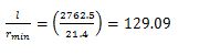
Step 4: Safe load
From IS:800-1984, allowable working stress in compression for the steel having yield stress as 260 N/mm2 σac =57.56 N/mm2 (MPa)
The safe load carrying capacity ![]()
The angle section lighter in weight than this is not suitable. Hence the design is satisfactory.
Step 5: Check for width of outstanding leg
Width of outstanding leg to thickness ratio ![]()
Hence, satisfactory. Provide ISA 110 mm x 110 mm x 10 mm (ISA 110 110@0.165 kN/m) for discontinuous strut.
Alternatively:
Step 2: Properties of trial section
From IS:808-1984, try angle section 120 x 120 x 10 (@ 18.2 kg/m)
Sectional area, A=2320 mm2, rxx=ryy=36.7 mm, ruu=46.3 mm, rvv=23.6 mm
Step3: Slenderness ratio
Effective length of strut is 2762.5 mm
Minimum radius of gyration rmin=23.6 mm
Slenderness ratio ![]()
Step 4: Safe load carrying capacity
From IS:800-1984 for l/r=117.055 and the steel having yield stress, fy=260 N/mm2, allowable working stress in compression
![]()
Safe load carrying capacity ![]()
The angle section lighter in weight than this is not suitable. Hence the design is satisfactory.
Example 11.8 Design a double angle discontinuous strut to carry 150 kN load. The length of strut between centre to centre of intersections is 4 m
Design:
Step 1: Selection of trial section
Assuming that the strut is connected to both sides of gusset 10 mm thick by two or more than two rivets.
Length of strut L= 4.00 m
Effective length of strut l=0.85L=(0.85 x 4) = 3.40 m.
The slenderness ratio of a double angle discontinuous strut and the value of yield stress for the steel may be assumed as 120 and 260 N/mm2, respectively.
Therefore, allowable stress in compression σac =64 N/mm2 (MPa)
Effective sectional area required ![]()
Step 2: Properties of trial section
From steel section tables (properties of two angles back to back), try 2 ISA 100 mm x 65 mm x 8 mm (2 ISA 100 65,@0.099 kN/m)
Sectional area A=2514 mm2, rxx=31.6 mm,
For angles having 10 mm distance back to back and long legs vertical ryy=27.5 mm
Therefore rmin=27.5 mm
Step 3: Slenderness ratio
Slenderness ratio 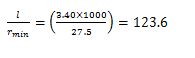
Step 4: Safe load
From IS:800-1984, allowable working stress in compression for the steel having yield stress as 260 N/mm2 σac =61.48 N/mm2 (MPa)
The safe load carrying capacity ![]()
The angle section lighter in weight than this is not suitable. Hence the design is satisfactory. Provide 2 ISA 100 mm x 65 mm x 8 mm for the strut. Provide tacking rivets 18 mm in diameter at 500 mm spacing.
Last modified: Saturday, 5 October 2013, 7:46 AM