Site pages
Current course
Participants
General
MODULE 1.
MODULE 2.
MODULE 3.
MODULE 4.
MODULE 5.
MODULE 6.
MODULE 7.
MODULE 8.
MODULE 9.
MODULE 10.
MODULE 11.
MODULE 12.
LESSON 12. Design of Colum Bases-Slab Base
12.1 INTRODUCTION
The columns are supported on the column bases. The column bases transmit the column load to the concrete or masonry foundation blocks. The column load is spread over large area on concrete or masonry blocks. The intensity of bearing pressure on concrete or masonry is kept within the maximum permissible bearing pressure. The safety of the structure depends upon stability of foundation. The column bases should be designed with utmost care and skill. In the column bases, intensity of pressure on concrete block is assumed to be uniform. The column bases shall be of adequate strength, stiffness and area to spread the load upon the concrete, masonry, other foundation or other supports without exceeding the allowable stress on such foundation under any combination of the load and bending moments. The column bases are of two types;
- Slab base, and
- Gusseted bases
The column footings are designed to sustain the applied loads, moments and forces and the induced reactions. The column load is spread over large area, so that the intensity of bearing pressure between the column footing and soil does not exceed the safe bearing capacity of the soil. it is ensured that any settlement which may occur shall be as nearly uniform as possible and limited to an accepted small amount. The column load is first transmitted to the column footing through the column base. It is then spread over the soil through the column footing. The column footings are of two types;
- Independent footings, and
- Combined footings.
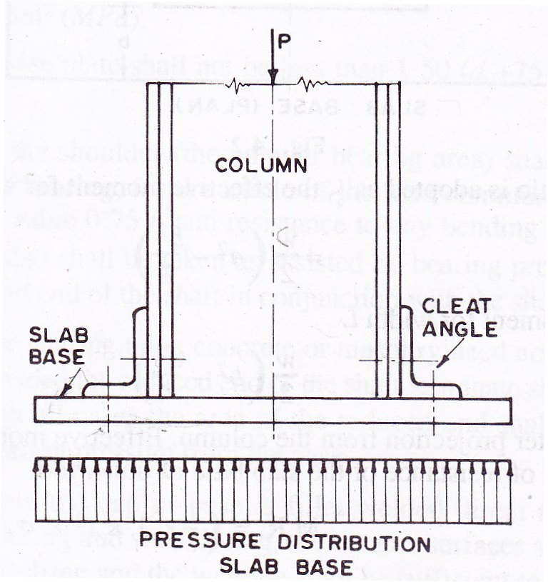
12.2 SLAB BASE
The slab base as shown in Fig. 12.1 consists of cleat angles and base plate. The column end is faced for bearing over the whole area.
The gussets (gusset plates and gusset angles) are not provided with the column with slab bases. The sufficient fastenings are used to retain the parts securely in plate and to resist all moments and forces, other than the direct compression. The forces and moments arising during transit, unloading and erection are also considered. When the slab alone distributes the load uniformly the minimum thickness of a rectangular slab is derived as below;
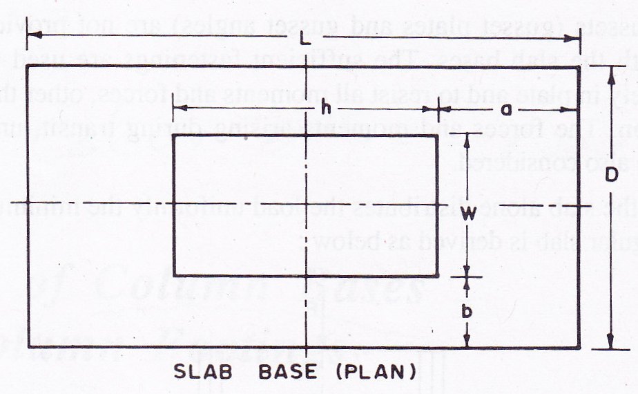
The column is carrying an axial load P. Consider the load distributed over area h x w and under the slab over the area L x D as shown in Fig. 12.2.
Let t=Thickness of the slab
W=Pressure or loading on the underside of the base
a=Greater projection beyond column
b=Lesser projection beyond column
σbs= Allowable bending stress in the slab bases for all steels, it shall be assumed as 185 N/mm2
Consider a strip of unit width.
Along the xx-axis ![]()
Along the yy-axis ![]()
If Poison ratio is adopted as ¼ the effective moment for width D ![]()
Effective moment for width L ![]()
Since a is greater projection from the column, the effective moment for width D is more. Moment of resistance of the slab base of unit width
![]()
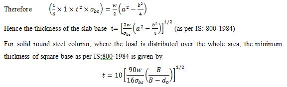
Where t= Thickness of plate in mm
W=Total axial load in kN
B=Length of the side of base of cap in mm
d0=Diameter of the reduced end (if any) of the column in mm
σbs= Allowable bending stress in steel (is adopted as 185 N/mm2)
The allowable intensity of pressure on concrete may be assumed as 4 N/mm2. When the slab does not distribute the load uniformly or where the slab is not rectangular, separate calculation shall be made to show that stresses are within the specified limits.
When the load on the cap or under the base is not uniformly distributed or where end of the column shaft is not machined with the cap or base, or where the cap or base is not square in plan, the calculations are made on the allowable stress of 185 N/mm2 (MPa). The cap or base plate shall not be less than 1.50 (do+75) mm in length or diameter.
The area of the shoulder (the annular bearing area) shall be sufficient to limit the stress in bearing, for the whole of the load communicated to the slab to the maximum value 0.75 fy and resistance to any bending communicated to the shaft by the slab shall be taken as assisted by bearing pressures developed against the reduced and of the shaft in conjunction with the shoulder.
The bases foe bearing upon concrete or masonry need not be machined on the underside provided the reduced end of the shaft terminate short of the surface of the slab and in all cases the area of the reduced end shall be neglected in calculating the bearing pressure from the base.
In cases where the cap or base is fillet welded direct to the end of the column without boring and shouldering, the contact surfaces shall be machined to give a perfect bearing and the welding shall be sufficient to resist transmitting the forces specified above. Where the full length T butt welds are provided no machining of contact surfaces shall be required.
Example 12.1 A column section HB 250,@ 0.510 kN/m carries an axial load of 600 kN. Design a slab for the column. The allowable bearing pressure on concrete is 4 N/mm2. The allowable bending stress in the slab base is 185 N/mm2(MPa).
Design:
Step 1: Area of slab base required
Axial load of column = 600 kN
It is assumed uniformly distributed under the slab
Area of the slab base required ![]()
The length and width of slab base are proportioned so that projections on either side beyond the column are approximately equal.
Size of column section HB 250,@ 0.510 kN/mm is 250 mm x 25 mm
Area of slab base =(250+2a)(250+2b) mm2
Step 2: Projections of base plate
Let projections a and b are equal
Area of slab (250+2a)2 = 15 x 104. Therefore a=68.45 mm
Provide projections a=b=70 mm
Provide slab base (250 + 2 x 70) (250 + 2 x 70) = 390 mm x 390 mm
Area of slab provided = 390 x 390 = 1,52,100 mm2
Intensity of pressure from concrete under slab ![]()
Step 3: Thickness of slab base:
Thickness of slab ![]()
Provide 16 mm thick slab base. The fastenings are provided to keep the column in position.
Example 12.2 A column section SC 250,@ 85.6 carries an axial load of 600 kN. Design a slab base for the column. The allowable bearing pressure on concrete is 4 N/mm2. The allowable bending stress in the slab base is 185 N/mm2(MPa).
Design:
Step 1: Area of slab base required
Axial load of column is 600 kN. It is assumed uniformly distributed under the slab.
Area of slab base required ![]()
The length and width of slab base are proportioned so that the projections on either side beyond the column are approximately equal.
Size of column section SC 250,@ 85.6 kg/m = 250 mm x 250 mm
Area of slab base = (250 + 2a)(250+2b) mm2
Step 2: Projections of base plate
Let the projections a and b be equal.
Area of slab (250+2a)2 = 15 x 104. Therefore a=68.45 mm
Provide projections a=b=70 mm
Provide slab base (250 + 2 x 70) (250 + 2 x 70) = 390 mm x 390 mm
Area of slab provided = 390 x 390 = 1,52,100 mm2
Intensity of pressure from concrete under slab
Step 3: Thickness of slab base:
Thickness of slab ![]()
Provide 16 mm thick slab base. The fastenings are provided to keep the column in position.
Last modified: Saturday, 5 October 2013, 8:16 AM