Site pages
Current course
Participants
General
MODULE 1.
MODULE 2.
MODULE 3.
MODULE 4.
MODULE 5.
MODULE 6.
MODULE 7.
MODULE 8.
MODULE 9.
MODULE 10.
MODULE 11.
MODULE 12.
LESSON 15. Cement Concrete
15.1 INTRODUCTION
Cement concrete consist of hard inorganic materials called aggregates such as gravel, sand, crushed stone, slag etc. cemented together with Portland cement and water. It is a mixture of aggregates and cement-water paste. The cement-water paste has its role to bind the aggregates to form a strong rock like mass after hardening as a consequence of the chemical reaction between cement and water. Aggregates are classified into fine aggregates and coarse aggregates. Fine aggregates consist of sand whose particle size does not exceed 4.75 mm. Course aggregates consist of gravel, crushed stone etc., of particle size more than 4.75 mm. the cement-water paste acts as a slurry which fills the voids in sand forming mortar. The mortar so formed fills the voids in the coarse aggregates. When the above materials are mixed together so as to form a workable mixture, it can be moulded or cast into beams, slabs etc. A few hours after mixing, the materials undergo a chemical combination and as a consequence, the mixture solidifies and hardens, attaining greater strength with age.
Even though the structural design may be absolutely safe and satisfactory, if the concrete made in the construction of the structure is defective, the result will be a weak structure liable to failure and it cannot be rectified or made up and will remain forever. Concrete possesses a high compressive strength and is usually more economical than steel and is not subjected to corrosive weathering and such effects. Hence concrete is used in all present day constructions. But, concrete has a poor tensile strength and is liable to be craked when subjected to tension. It also develops shrinkage stresses. Hence, by providing steel reinforcement within the concrete mass at the time of pouring, the resulting member will have both the properties of concrete and steel. By reinforcing the concrete with steel, the defects of concrete are made good.
15.2 REQUIREMENTS OF GOOD CONCRETE
In making sound and durable concrete the prime requirements are the following:
-
The aggregates should be hard and durable.
-
The aggregates shall be properly graded in size from fine to course.
-
Cement should be of sufficient quantity to produce the required water-tightness and strength
-
The water used while mixing shall be free from organic material or any deleterious minerals.
-
The quantity of water should be such as to produce the needed consistency.
-
Mixing should be done thoroughly so as to produce homogeneity.
-
Concrete should fill every part in the form. This is done by ramming or puddling.
-
Until the concrete is thoroughly hard it is necessary to ensure that the temperature of concrete is maintained above the freezing point. This is done to avoid retarded hardening.
15.3 GRADES OF CONCRETE
In construction certain standard mixes alone are used. A set of mix for concrete should be well defined either in terms of the proportion of cement, fine and course aggregate or in terms of the 28-days compressive strength requirements
15.3.1 Concrete mix in terms of proportions of the components.
The usual mixes and its uses are given below
The mix 1:3:6 is used for mass concreting and the rear sides of dams.
The mix 1:2:4 is used for general reinforced concrete work. The revised I.S. Code has recommended the mix 1:1½:3 for general reinforced concrete work.
The mix 1:1½:3 is used for front faces of dams, water tanks, columns etc.
The mix 1:1:2 is used for piles.
15.3.2 Concrete mix based on the 28-days cube strength
The usual grades of concrete are given in the following table.
Table 15.1 Grades of concrete based on the 28-days cube strength
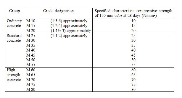
The I.S. 456:2000 code has recommended that the minimum grade of concrete for plain and reinforced concrete work is M 20. In the above table characteristic strength means the strength of material below which not more than 5 per cent of the test results are expected to fall.
15.4. PROPERTIES OF CONCRETE
Strength, durability and workability may be considered as the main properties of concrete. In addition, good concrete should be able to resist wear and corrosion and it should be water-tight, compact and economical.
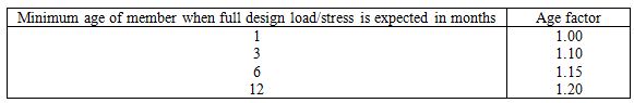
15.4.1 Increase in strength with age
Where it can be shown that a member will receive its full design load/stress within a period of 28-days after the casing of the member (for example, in foundation and lower columns in multistory buildings), the characteristic compressive strength given in the Table 15.1 may be increased by multiplying by the factors given in the Table 15.2.
Table 15.2 Age factor
Note:
-
No increase in respect of age at loading should be allowed where high alumina cement concrete is used.
-
Where members are subjected to lower direct load during construction, they should be checked for stresses resulting from combination of direct load and bending during construction
-
The permissible stresses or design strengths shall be based on the increased value of the compressive strength.
15.4.2 Tensile strength of concrete
The flexural and split tensile strengths shall be obtained as described in I.S.516 and I.S.5816 respectively. When the designer wishes to use an estimate of the tensile strength from the compressive strength, the following formula may be used:
Flexural strength ![]()
Where fck = characteristic compressive strength of concrete in N/mm2.
15.4.3 Shearing strength of concrete
Concrete really has a large shearing strength. Generally the shearing strength as such does not have any worthy significance, since the shear stresses are in all cases limited to much lower values so as to protect the concrete against failure by diagonal tensile stresses.
The modulus of elasticity is normally related to the compressive strength of concrete. The modulus of elasticity is primarily influenced by the elastic properties of the aggregate and to a lesser extent by the conditions of curing and age of the concrete, the mix proportions and the type of cement. In the absence of test data, the modulus of elasticity for structural concretemay be assumed as ![]()
Where Ec=The short term static modulus of elasticity in N/mm2 and
fck=The characteristic cube strength of concrete in N/mm2
15.4.4 Durability
Concrete can be made durable by using good quality materials (cement, aggregates and water) by reducing the extent of voids by suitable grading and proportion of the materials, by using adequate quantity of cement and low water cement ratio thereby ensuring concrete of increased permeability. In addition, thorough mixing, desired placing, adequate compaction and curing of the concrete is equally important to have durable concrete.
15.4.5 Workability
Workability is the most elusive property of concrete and is quit difficult to define and measure. In the simplest form a concrete is said to be workable if it can be easily mixed, handled, transported, placed in position and compacted. A workable concrete mix must be fluid enough so that it can be compacted with minimum labour. A workable concrete does not result in bleeding or segregation. Bleeding of concrete takes place when the excess of water in the mix comes up at the surface and segregation is caused when coarse aggregates have a tendency to separate from the fine aggregates.
15.4.6 Shrinkage of concrete
Concrete undergoes shrinkage as it loses moisture by evaporation. The withdrawal of moisture is never uniform throughout the concrete mass, resulting in differential shrinkage. Such differential shrinkage produces internal stresses. In ordinary concrete the amount of shrinkage depends on the exposure condition and the quality of concrete. Exposure to wind increases shrinkage. A humid atmosphere decreases shrinkage low humidity increases shrinkage. For a given environment, the total shrinkage of concrete is most influenced by the total amount of water present in the concrete at the time of mixing and to a leasser extent by the cement content. In the absence of test data, the approximate value of the total shrinkage strain may be taken as 0.0003 (For additional information see IS 1343)
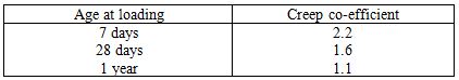
As concrete is subjected to loading, the initial strain in concrete at low unit stresses is nearly elastic. But over a period of time this strain increases even under constant load. This increases the deformation of a loaded member which takes place over a period of time is called creep. Factors contributing to creep are, loading at early age, using concrete of high water cement ratio, exposing concrete to drying conditions. Creep co-efficient is the ratio of the ultimate creep strain to the elastic strain at the age of loading. In the absence of experimental data the creep co-efficient may be taken as per the Table 15.3. The ultimate creep strain does not include the elastic strain.
Table 15.3 Creep co-efficient
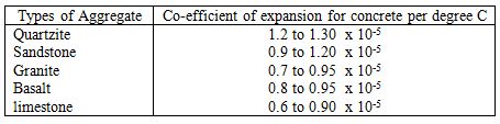
15.4.7 Thermal expansion
The co-efficient of thermal expansion for concrete may be taken at the values given in Table 15.4.
Table 15.4 Thermal expansion
15.5 STRENGTH OF CONCRETE
Strength of concrete means the ultimate resisting capacity against the action of loads. Under standardized sample and loading conditions, concrete can be characterized by the load intensity it can resist. Generally the crushing stress of 150 mm cube of concrete is taken to represent the strength of concrete. These days the crushing stress of 150 mm cube of concrete is taken to represent the grade or the quality of concrete.
In the earlier days it was believed that the strength of concrete would increase by using more cement and greater compaction. The role of water was taken only to render concrete to a sufficient plastic state to be compacted easily. Now it is well known that the compressive strength of fully compacted concrete is inversely proportional to the water-cement ratio. To day it is established that the strength of concrete can be enhanced by decreasing the water-cement ratio, increasing the fineness of cement, by age of concrete, by increasing the size of aggregate and by proper grading and shape of aggregates.
15.6 PERMISSIBLE STRESSES IN CONCRETE (I.S. 456-2000)
The I.S. code has specified the permissible stresses in concrete for various grades. They are given in the Table 15.5
Table 15.5 Permissible stress in concrete in compression and average bond
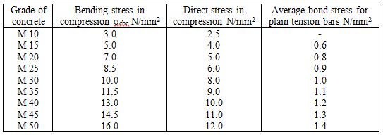
Note: 1. The bond stress given above shall be increased by 25 per cent for bars in compression.
2. The bond stress given above shall be increased by 40 per cent for deformed bars.
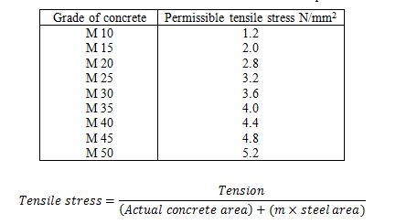
Table 15.6 Permissible direct stress in tension in concrete based on equivalent concrete area
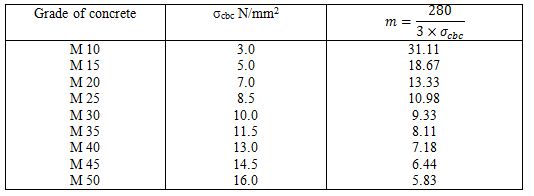
15.7 MODULAR RATIO m
This is the ratio of modulus of elasticity for steel to the modulus of elasticity for concrete. As per the code, the modular ratio shall be taken as ![]()
Where σcbc = Permissible compressive stress in concrete in bending. The values of modular ratio for different grades of concrete are given in the Table 15.7.
Table 15.7 Modular ratio for different grades of concrete
15.8 PERMISSIBLE SHEAR STRESS IN CONCRETE
The I.S. code has introduced the concept of nominal shear stress defined by the following relation.
Nominal shear stress in beams or slabs of uniform depth ![]()
Where V= Shear force due to design loads
b = Breadth of the member (or breadth of web)
d = Effective depth
In the case of beams of varying depth ![]()
Where, M=Bending moment at the section and
β = angel between the top and bottom edges of the beam
The negative sign in the formula should be used when the bending moment increases numerically in the same direction as the effective depth increases; and the positive sign in the formula should be used when the bending moment decreases numerically in this direction. The permissible shear stress in concrete in beams without shear reinforcement is given in the Table 15.8.
Table 15.8 Permissible shear stress in concrete in beams
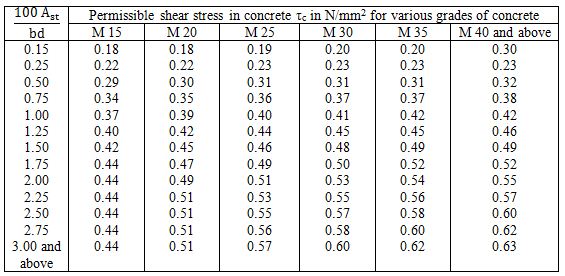
Note: Ast is that area of longitudinal tension reinforcement which continues at least one effective depth beyond the section being considered except at supports where the full area of tension reinforcement may be used.
15.9 REINFORCEMENT
Reinforcement used shall confirm to the requirements of I.S. 432 specification for mild steel and high tensile steel bars and hard drawn steel wire for concrete reinforcements (Revised). The reinforcement shall be free from loose mill scale, loose rust, oil and grease or any such harmful matter, immediately before placing the concrete. The reinforcement shall be placed and positioned strictly following the requirements shown in the structural drawings. Bending bars are expected to fulfill certain definite functions and hence bars must be bent so that there is good advantage of the worked design. Bending bars shall be done with greater caution. Often this job does not receive that much attention which it deserves. There are instances of failure of structures for want of correct bending even though the designs worked out are not faulty.
15.10 THE NECESSITY OF BENDING REINFORCEMENT
Bars are bent under different circumstances. They may be bent to form hooks so as to develop proper anchorage. Sometimes bars have to be bent so as to form loops as in the case of stirrups as shear reinforcement. They may also be bent up to form necessary reinforcement for hogging bending moments. The following are the types of bend we normally come across and are in Fig. 15.1
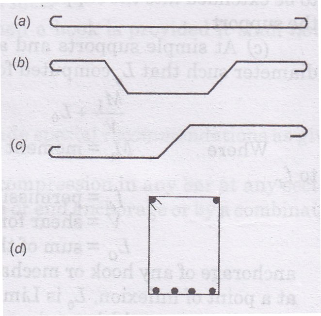
-
Hooks at the end of mild steel bars in beams.
-
Bars bent up at ends and hooked in beams for resisting diagonal tension.
-
Bars which serve for positive bending moment which are bent up to resist negative bending moment.
-
Bars bent to form loops to serve as shear reinforcement.
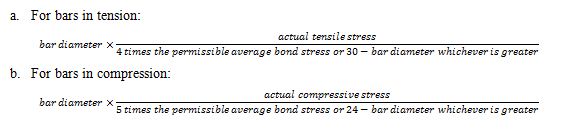
15.10.1 Splices in tensile reinforcement
Splices at point of maximum tensile stress shall be avoided wherever possible; splices where used shall be welded, lapped or otherwise fully developed. In any case the splice shall transfer the entire computed stress from bar to bar. Lapped splices in tension shall not be used for bars of sizes larger than 36 mm diameter and such splices shall preferably be welded. For contact splices, spaced laterally closer than 12-bar diameters or located closer than 150 mm or 6-bar diameters from the outside edge, the lap shall be increased by 20 percent or stirrups or closely spaced spirals shall enclose the splice for its full length. Where more than one half of the bars are spliced within a length of 40-bar diameters or where splices are made at points of maximum stress special precaution shall be taken such as increasing the length of the lap and/or using spirals of closely spaced stirrups around and for the length of the splice.
15.10.2 Splices in compression reinforcement
Where lapped splices are used, the lap length shall confirm to the requirements. Welded splices may be used instead of lapped splices. Where bar size exceeds 36 mm diameter welded splices shall preferably be used. In bars required for compression only the compressive stress may be transmitted by bearing the square cut ends held in concrete contact by a suitably welded sieve or mechanical device.
In columns where longitudinal bars are offset at a splice, the slope of the inclined portion of the bar with the axis of the column shall not exceed 1 in 6 and the portions of the bar above and below the offset shall be parallel to the axis of the column. Adequate horizontal support at the offset bands shall be treated as a matter of design and shall be provided by metal ties, spirals or parts of the floor construction. Metal ties or spirals so designed shall be placed near (not more than eight-bar diameters from) the point of bend. The horizontal thrust to be resisted shall be assumed as 1½ times the horizontal component of the nominal stress in the inclined portion of the bar. Offset bars shall be bent before they are placed in forms.
15.11 TYPES AND GRADES OF REINFORCEMENT BARS
The Table 15.9 shows the various types of steel permitted for use as reinforcement bars and their characteristic yield strengths fy. The Table 15.10 shows the permissible stresses in steel reinforcement.
Table 15.9 Various types of steel permitted for use as reinforcement bars
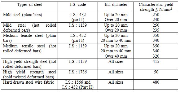
Table 15.10 Permissible stresses in steel reinforcement (I.S. 456)

15.12 JOINING OR LAPPING
15.12.1 Length of lap
The length of lap in reinforcement shall not be less than:
15.12.2 Minimum spacing of reinforcement
The minimum horizontal distance between parallel reinforcement shall not be less than the following:
- Diameter of bar when bars are of the same diameter and diameter of the thickest bar when bars of more than one size are used
- Maximum size of coarse aggregate plus 5 mm. a greater distance should be provide when convenient.
The vertical distance between two horizontal main bars shall be not less than 15 mm, two-thirds the nominal maximum size of aggregate or the maximum size of bar whichever is greatest.
15.12.3 Cover
All reinforcements shall have a cover of concrete and the thickness of such a cover exclusive of plaster or other decorative finish shall be as follows:
-
At each end of a reinforcing bar–not less than 25 mm nor less than twice the diameter of such bar.
-
For longitudinal reinforcement in a column–not less than 40 mm nor less than the diameter of bar. In the case of columns of minimum dimension of 200 mm or less, whose bars do not exceed 12 mm dia-25 mm cover may be used.
-
For longitudinal reinforcement in beams–not less than 25 mm nor less than diameter of such bar.
-
For tensile, compressive, shear and other reinforcement in a slab–not less than 15 mm nor diameter of reinforcement.
-
For any other reinforcement–not less than 15 mm nor less than the diameter of reinforcement.
For reinforced concrete members totally immersed in sea water, the cover shall be 50 mm more than that specified above. For concrete of grade over M 25 the additional thickness of cover may be reduced to half the value stipulated above. In all cases the cover should not exceed 75 mm.
15.13 USEFUL CONSTANT OF STEEL
Modulus of elasticity 2 x 10⁵ N/mm2
Poisson’s ratio 0.25 to 0.30
Modulus of rigidity 7 x 10⁴ to 8 x 10⁴ N/mm2
Coefficient of thermal expansion 12 x 10-6 per ˚C
Specific weight 7.85 x 10⁴ N/m3
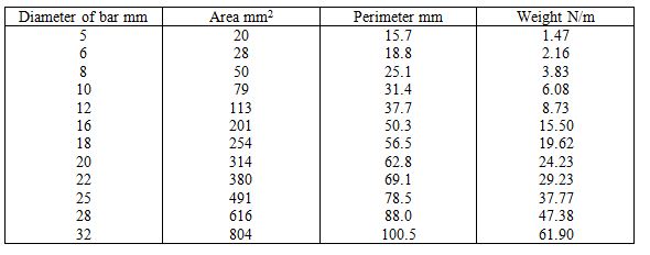
Table 15.11 Area, Perimeter and weights of round bars
Last modified: Saturday, 5 October 2013, 8:19 AM