Site pages
Current course
Participants
General
MODULE 1.
MODULE 2.
MODULE 3.
MODULE 4.
MODULE 5.
MODULE 6.
MODULE 7.
MODULE 8.
MODULE 9.
MODULE 10.
MODULE 11.
MODULE 12.
LESSON 16. Analysis of Singly Reinforced Section
16.1 INTRODUCTION
In working stress method it will be assumed that concrete and steel are elastic and they are subjected to such stresses that the components remain elastic and the maximum stresses included in the components do not exceed the allowable stresses. This method has certain shortcomings. For concrete, the relation between stress and strain is not linear but follows a curve. Though the stress-strain relation is linear for mild steel it is not so in the case of high yield strength deformed bars which are most commonly used in practice. This method does not provide a true factor of safety against failure or objectionable deformation. The method ignores the effect of creep and shrinkage of concrete.
A reinforced concrete member shall be designed for all conditions of stresses that may occur and in accordance with the principles of mechanics. The characteristic property of a reinforced concrete member is that its components namely concrete and steel act together as a single unit as long as they remain in the elastic condition i.e., the two components are bound together so that there can be no relative displacement between them.
16.2 REINFORCED CONCRETE MEMBERS SUBJECTED TO DIRECT LOAD
Let us consider a reinforced concrete member of length l
Let Asc=area of steel and
Ac =area of concrete
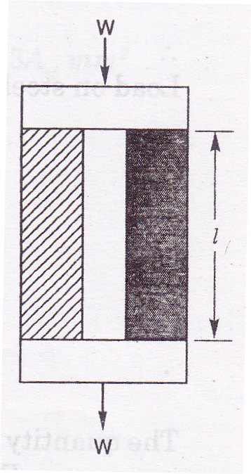
For the sake of analysis the two components have been shown separately in Fig. 16.1. Let the member be subjected to an axial load W. Let Ws and Wc be the load components transmitted to steel and concrete respectively. Assuming both the components undergo same change in length.
Strain in steel = Strain in concrete
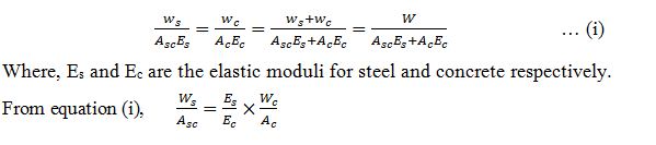
Hence we find that the steel member is subjected to a greater load than concrete. This explains, that when steel is provided in combination with concrete, it will be very useful in sharing a considerable part of the load on the composite member.
16.3 EQUIVALENT OR TRANSFORMED CONCRETE AREA
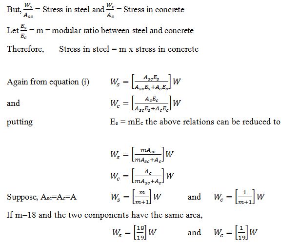
Let fs and fc be the stresses in steel and concrete. Since strains are equal in steel and concrete,
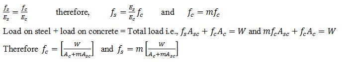
The quantity (Ac+mAsc) is called the equivalent concrete area
Equivalent concrete area = Ac = Actual concrete area + (m x steel area)
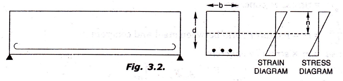
16.4 COMPOSITE MEMBER SUBJECTED TO BENDING
Consider and reinforced concrete beam simply supported on a span l. Let us consider the mid section of the beam. Let b be the width of the beam and d the depth of the beam from the top compression edge to the centre of steel. Fig. 16.2 shows the strain and stress diagrams for concrete at the section. We assume that the strain varies linearly consistent with the assumption that transverse sections which were plane before bending remain plane after bending. With the assumption of no slip between steel and the surrounding concrete, it means, that the strains in steel and the surrounding concrete are equal. Suppose the strain in concrete at the level of the steel is e, then the strain in steel is also equal to e. the corresponding stresses in concrete and steel at the same level will be eEc and eEc respectively. Thus we find the stress in steel is again modular ratio times the stress in concrete at the level of steel.
We know that in the case of beams of homogeneous material the neutral axis is a centroidal axis. In the case of composite section the neutral axis can be determined by considering the equivalent or transformed section of one material only. The neutral axis therefore is the centroidal axis of this equivalent section. This treatment is satisfactory when the components of the beam remain as one unit in the elastic condition. For instance in the case of a composite beam considering of a timber beam strengthened by steel plates, the analysis can be made by replacing steel by its equivalent timber section and taking the neutral axis at the centroid of the transformed section. But concrete is a material strong in compression and weak in tension. After the concrete is strained beyond a limit it develops cracks in tension zone. After this stage the concrete in the tension zone becomes ineffective to offer tensile resistance. This condition shifts the position of the neutral axis. Hence, the neutral axis has to be determined ignoring the concrete in the tension zone.
Example 16.1 A 300 mm x 300 mm R.C. member reinforced with 1257 mm2 of steel supports an axial compressive load of 440 kilonewtons. Calculate the stresses in concrete and steel. Take m=13.33
Solution
A = 300 x 300 = 90000 mm2
Asc=1257 mm2 therefore Ac = 90000-1257 = 88743 mm2
Equivalent concrete area = Ae = Ac+mAsc=88743+(13.33x1257)=105498.81 mm2
Compressive load = W = 440 kilonewtons = 440000 newtons
![]()
Stress in steel ![]()
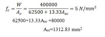
Example 16.2 A 250 mm x 250 mm reinforced concrete member has to support an axial compressive load of 400 kilonewtons. If the stress in concrete is not to exceed 4 N/mm2, calculate the area of steel required. Take m=13.33.
Solution
A = 250 x 250 = 62500 mm2
Asc = area of steel =?
Ac = (62500-Asc)
Equivalent concrete area Ae = Ac+mAsc =(62500-Asc)+(13.33 Asc) mm2=62500+13.33Asc mm2
Limiting the stress in concrete to 5 N/mm2
16.5 SINGLY REINFORCED BEAMS
A singly reinforced beam is a beam provided with longitudinal reinforcement in the tension zone only. The analysis and design of a reinforced concrete member subjected to bending are based on the following assumptions:
-
Plane sections transverse to the centre line of a member before bending remain plane sections after bending.
-
Elastic modulus of concrete has the same value within the limits of deformation of the member.
-
Elastic modulus for steel has the same value within the limits of deformation of the member.
-
The reinforcement does not slip from concrete surrounding it.
-
Tension is borne entirely by steel.
-
The steel is free from initial stresses when embedded in concrete.
-
There is no resultant thrust on any transverse section of the member
Of the above assumption, the assumption that plane sections transverse to the centre line of a member before bending remain plane sections after bending is further explained below.
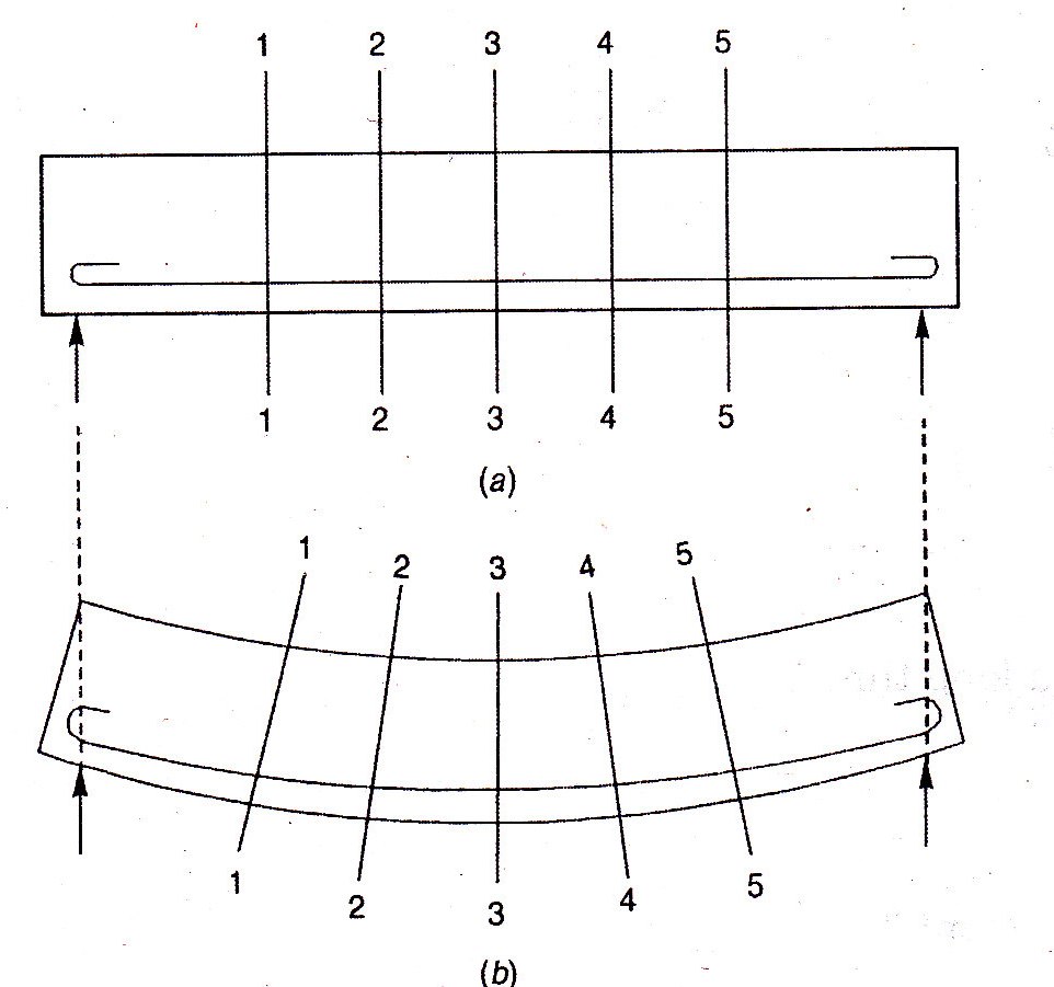
Fig. 16.3.a. shows a beam subjected to an external loading. Consider sections 1-1, 2-2, 3-3, 4-4, 5-5, etc, which are at right angles to the centre line of the member. After the beam bends, the various fibres are subjected to deformations of such amounts that these planes respectively occupy the new positions shown in Fig.16.3.b. Fig.16.4.a. shows a simply supported singly reinforced beam. Consider two sections 1-1 and 2-2 unit distance apart. Let the beam subjected to an external loading. Fig.16.4.b. shows the deflected form of the beam. The upper most fibre of concrete AC deforms to A1C1. A fibre BD of concrete at the level of the reinforcement deforms to B1D1.
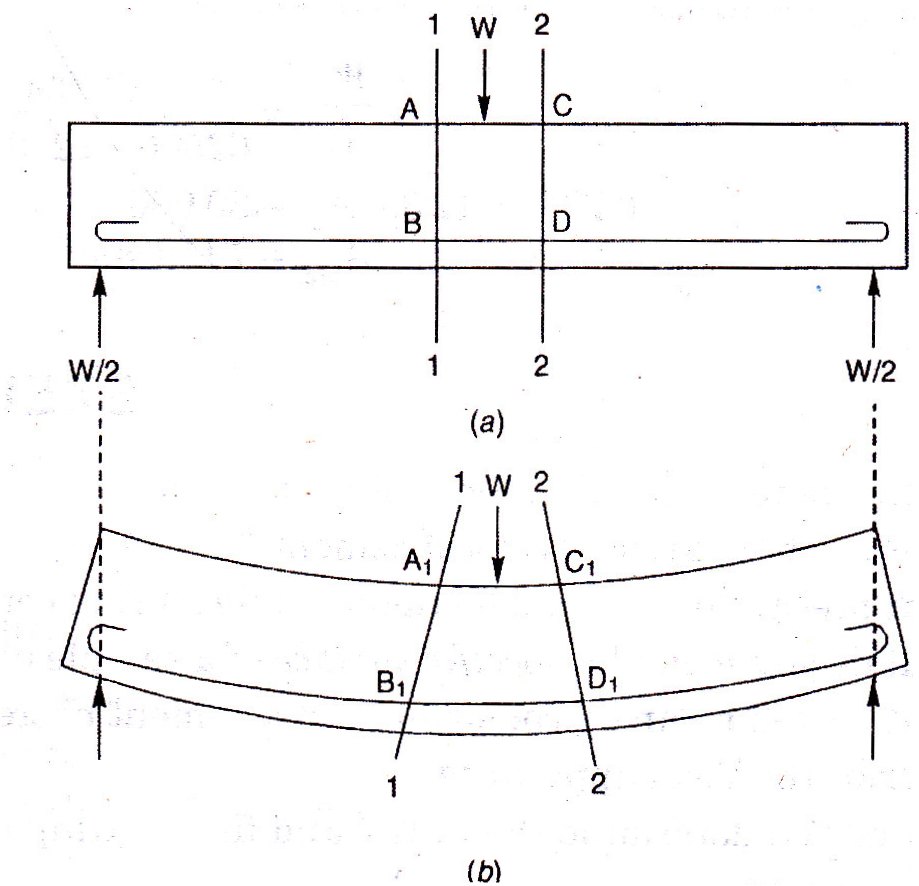
We have strain in concrete in the top fibre = AC-A1C1=ec
Similarly, strain in concrete just surrounding the steel = B1D1-BD=et
Since there is no slip between steel and the concrete surrounding it, the strain in steel is also equal to et.
Therefore stress in steel (t) = Eset = mEcet
Stress in concrete surrounding steel = ct = Ecet = Ec (1/Es)
Therefore ct = t/m.
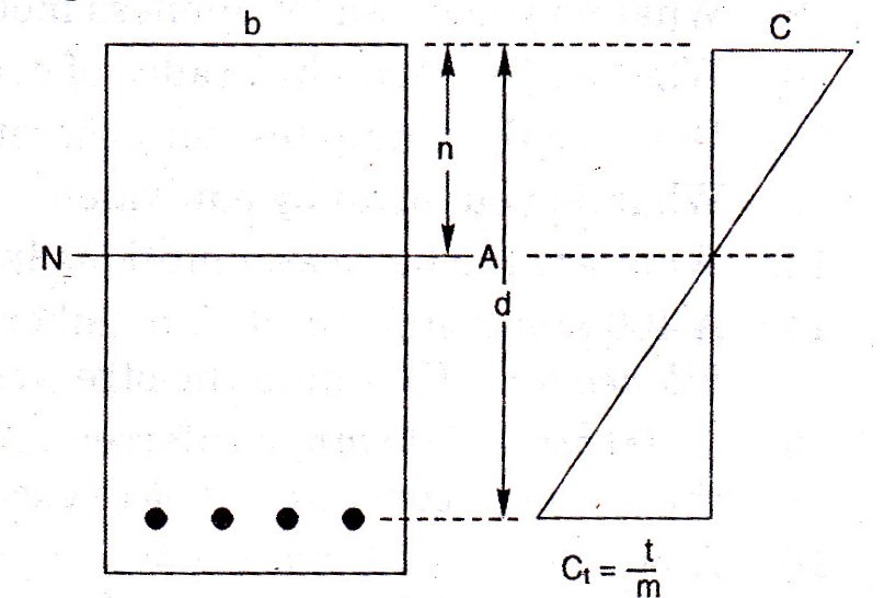
Fig. 16.5 shows the stress distribution in concrete across the section of the beam.
16.6 EFFECT OF REINFORCEMENT IN CONCRETE
Concrete has a very low tensile strength. Tensile strength of concrete is about one-tenth of its compressive strength. Hence in structural design, it is assumed that the tensile strength of concrete is nil. Thus it is necessary to reinforce (strengthen) concrete components which are subjected to tension. Such reinforcement is accomplished by providing steel bars which are meant to resist the entire tension.
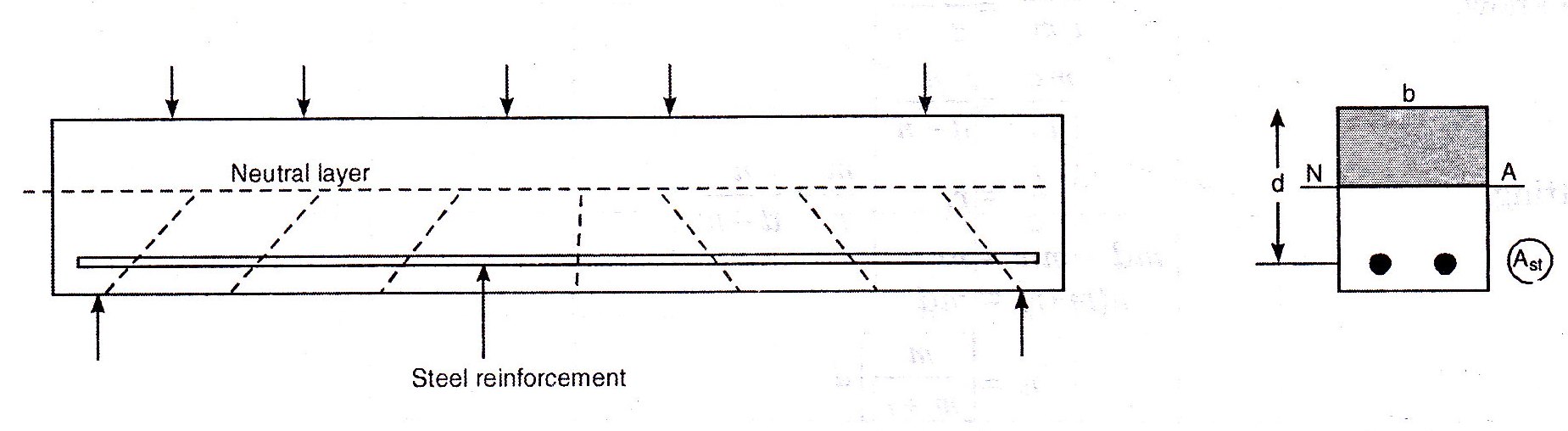
Consider the reinforced concrete beam shown in F.g.16.6. If the loading on the beam is gradually increased, the lower layer of the beam elongate and when such elongation exceeds the ultimate tensile strain of concrete, crakes will occur. We know the strain in section is proportional to the distance from the neutral axis. Hence as the loads are increased the tensile stresses also increase and consequently the crakes in number spread upward toward the neutral axis. These crakes will be at right angles to the direction of the maximum principal tensile stress in the concrete. Thus, the inclination of these cracks in concrete is related to bending, shear and axial stresses the section subjected to. As the concrete gets cracked, it will no longer be able to resist or transmit tensile forces. As this happens, the tensile force in the bottom of the beam has to be resisted entirely by the steel reinforcement, while the compressive forces at the top are resisted by concrete. Thus, for all practical purposes, the effective cross-section which resists flexure is as shown in Fig.16.6. The part of the section shown shaded above the neutral axis becomes the compressive zone, while the steel reinforcement alone offers the required tensile resistance resisting the tensile stresses below the neutral axis.
16.7 NEUTRAL AXIS
The neutral axis for a beam section is the line of intersection of the neutral layer with the beam section. This is a straight line dividing the cross-section into a tension and a compression zone. One of the basic assumptions made in the analysis of reinforced concrete beams is that the tension is borne completely by steel. Hence, it is important to note that in determining the neutral axis, the concrete in the tension zone should not be taken in to account. The tension should be considered as resisted entirely be the steel.
If the area of the reinforcement is Ast and the tensile stress in the reinforcement is t,
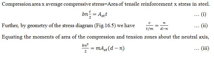
The total tension resisted, T = Ast t = Ast mct = (mAst) ct
Hence, a reinforcement of area Ast can be regarded as equivalent to an area (mAst) of the concrete. Let b and d be the breadth and effective depth of the beam section. Effective depth means the depth from the compression edge to the centre of the tensile reinforcement. Let n be the depth of neutral axis.
One of the assumption in the analysis is that there is no resultant thrust on the section i.e., the total compression is equal to the total tension. Therefore,
Position of neutral axis for a given percentage of steel:
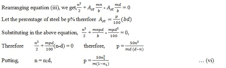
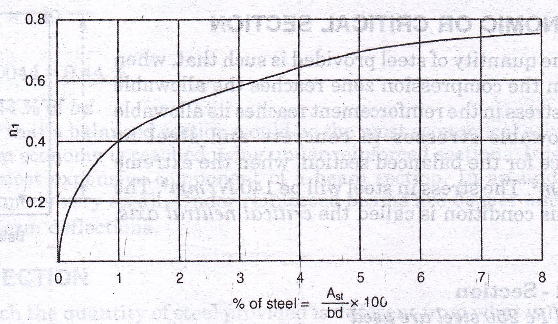
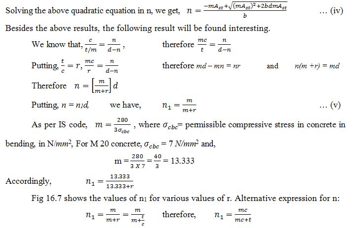
Fig. 16.8 shows the relation between the percentage of steel and the position of neutral axis for m=13.333.
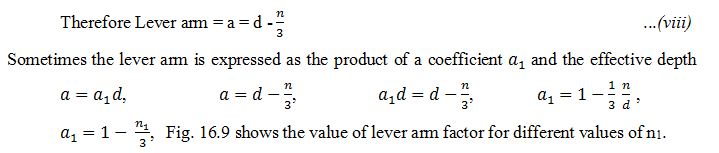
16.8. LEVER ARM
This is the distance between the line of action of the resultant compression and the line of action of the resultant tension. The line of action of the resultant compression is at the level of the centroid of the compressive stress diagrams. i.e. at the depth of ![]() from the compression edge.But the resultant tension is at the level of the reinforcement since the tensile resistance of concrete is ignored.
from the compression edge.But the resultant tension is at the level of the reinforcement since the tensile resistance of concrete is ignored.
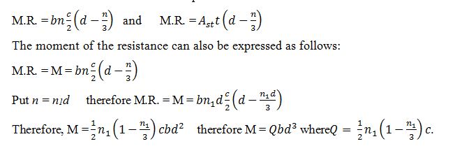
16.9 MOMENT OF RESISTANCE
This is the resisting moment offered by a beam section to resist the bending moment at the section.
Moment of resistance = Total compression or total tension x lever arm
16.10. BALANCED OR ECONOMIC OR CRITICAL SECTION
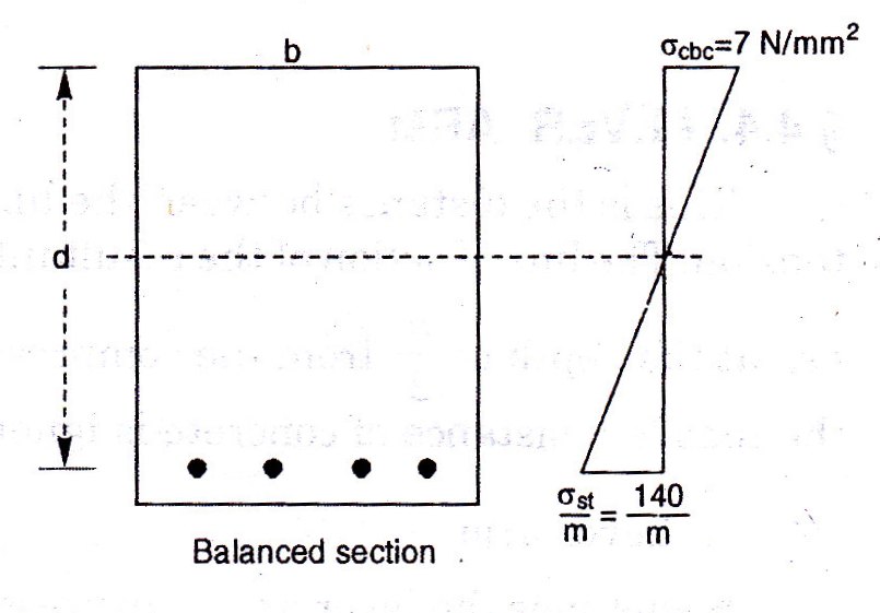
This is a section, in which the quantity of steel provided is such that, when the most distant concrete fiber in the compression zone reaches the allowable stress in compression, the tensile stress in the reinforcement reaches its allowable stress. For example let the allowable stresses in concrete and steel be 7N/mm2 and 140 N/mm2. Hence for the balanced section, when the extreme stress in concrete reaches 7N/mm2.The stress in steel will be 140 N/mm2. The neutral axis corresponding to this condition is called the critical neutral axis. Let nc be the depth of critical neutral axis as shown in the Fig. 16.10
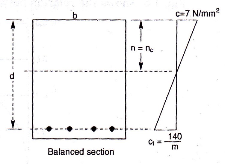
Analysis of the Balanced – Section
(i) When M 20 concrete and Fe 250 steel are used (Fig. 16.11), = 7 N/mm2, = 140 N/mm2
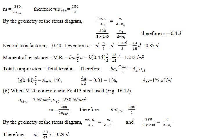

Neutral axis factor = n1 = 0.29
It may appear that a balanced section would be the most economical solution to design. This is not really true. In reality the maximum economy is reached using under reinforced sections. It is important to recognize that the steel reinforcement is the most expensive component of a beam section. In an under reinforced beam the ratio of volume of steel to total volume is very small. Under reinforced beams are deeper and stiffer and are not subjected to objectionable short or long term deflections.
16.11 UNBALANCED SECTION
This is a section in which the quantity of steel provided is different from what is required for the balanced section. Unbalanced sections may be classified into under-reinforced and over-reinforced sections.
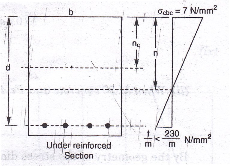
16.11.1 Under-Reinforced Section
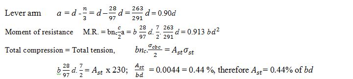
This is a section in which the quantity of steel provided is less than what is required for a balanced section. In this case when the stress in steel reaches its permissible value, the corresponding extreme compressive stress reached in concrete will be less than its permissible value. For example, taking the permissible stresses in concrete and steel as 7 N/mm2 and 230 N/mm2, we find that when the stress in steel reaches 230 N/mm2 , the extreme compressive stress in concrete will be less than 7 N/mm2 (Fig. 16.13). The depth n of the actual neutral axis will be less than the depth nc of the critical neutral axis. The moment of resistance of the section will be less than that of the balanced section.

Therefore, Moment of resistance of the section is given by,
![]()
the stress t being taken at the allowable stress for steel .
16.11.2 Over-Reinforced Section
This is a section in which the quantity of steel provided is more than what is required for a balanced section. In this case when the extreme compressive stress in concrete reaches its permissible value, the corresponding tensile stress in steel will be less than its permissible value. For example, taking the permissible stresses in concrete and steel as 7 N/mm2 and 230 N/mm2 (See Fig. 6.14). The depth n of the actial neutral axis will be greater than the depth of the critical neutral axis. The moment of resistance of the section will be greater than that of the balanced section.
Therefore Moment of resistance of the section is given
![]()
The stress c being taken at the allowable compressive stress for concrete .
Balanced design implies that there is just exactly enough amount of steel reinforcement to develop the maximum allowable compressive stress in concrete. If the amount of steel reinforcement provided is lesser, then the concrete compressive strength cannot be developed, and the section becomes under reinforced. The section becomes over reinforced if the amount of reinforcement provided is more than what is needed for a balanced section.
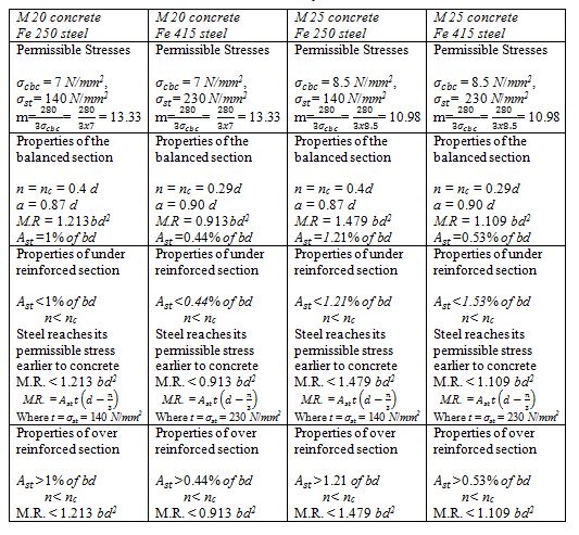
It may appear that a balanced design may prove to be the most economical design. This need not be true always. Often maximum economy is achieved by using under reinforced sections. This is because the reinforcing steel is the most expensive component of the section. Under reinforced beams, have greater depth providing greater stiffness and such beams are not subjected to objectionable deflections. The properties of reinforced section is summarized in Table 16.1
Table 16.1 Summary of Results
Last modified: Saturday, 5 October 2013, 8:21 AM