Site pages
Current course
Participants
General
MODULE 1.
MODULE 2.
MODULE 3.
MODULE 4.
MODULE 5.
MODULE 6.
MODULE 7.
MODULE 8.
MODULE 9.
MODULE 10.
MODULE 11.
MODULE 12.
LESSON 18. Analysis of Doubly Reinforced Sections
18.1 INTRODUCTION
A beam or slab reinforced with main steel both in tension and compression zones is said to be doubly reinforced. Often due to headroom considerations, architectural or some other such reasons, it is necessary to restrict the dimensions of a beam. The resisting moment of the beam with the limited dimensions, as worked out by the formula, MR=Rbd2, may be less than the bending moment the beam may be required to resist. In order that the beam may be safe, it is necessary to reinforce the beam in such a way that it is capable of developing the moment of resistance equal to the external bending moment.
The moment of resistance of the beam can be increased to a certain extent by gradually increasing the area of tensile reinforcement till the permissible stress in concrete is reached. This increase in resisting moment may not be sufficient to serve the purpose and hence the tensile steel will be necessary to be increased further. The further increase in tensile steel will cause a further increase in the compressive stress in concrete, which is not desirable. Hence in order to prevent the compressive stress in concrete from exceeding its safe permissible value, steel must be introduced in the compression zone to take up extra compressive stress. Thus the beam gets doubly reinforced.
A doubly reinforced section is generally provided under the following conditions;
-
When the depth and breadth of the beam are restricted and it has to resist greater bending moment than a singly reinforced beam of that section would do.
-
When the beam is continuous over several supports, the section of the beam at the supports is usually designed as a doubly reinforced section.
-
When the member is subjected to eccentric loading.
-
When the bending moment in the member reverses according to the loading conditions e.g., the wall of an underground R.C.C. storage reservoir, brackets etc.
-
When the member is subjected to shocks, impact or accidental lateral thrust.
18.2 Modular ratio for compression steel
A section reinforced with steel in compression and in tension zone is said to be doubly reinforced. The steel reinforcement provided in the compression zone is thus subjected to compressive stress. We know that when subjected to continuous compressive stress, concrete undergoes creep or plastic deformation (δ plastic) in addition to elastic deformation (δ elastic). In such a situation the value of the modulus of elasticity of concrete (Ec) is given by
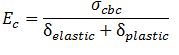
which obviously works out to be smaller than
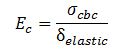
Thus the modulus of elasticity of concrete in compression works out to be smaller than that in tension. This calls for use of modified modular ratio for compression zone.
The code accordingly stipulates that modified value of modular ratio (mc) to be used for compression steel shall be = 1.5 m.
Hence compression stress in compression shall be calculated by multiplying the stress in the surrounding concrete by 1.5.
However, the compressive stress in compression steel thus calculated shall not exceed the permissible value of as given in Table 15.10.
It is observed that although adoption of mc = 1.5 m has very little effect on the moment of resistance of the section but it leads to higher value of stress in compression steel which results in considerable economy.
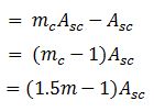
18.3 EQUIVALENT AREA OF STEEL IN COMPRESSION
In view of the above, the expression for equivalent area of steel in compression works out to be
18.4. LOCATION OF NEUTRAL AXIS
The location of neutral axis of a doubly reinforced beam can be determined by the following methods.
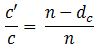
Method I. This method of finding the neutral axis is adopted when the stresses in concrete and steel are given. Since the stress diagram of a doubly-reinforced beam is identical to that of a singly-reinforced beam, we get
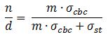
The value of neutral axis thus obtained is called critical neutral axis. Hence for given stresses, the depth of critical neutral axis (nc) for doubly-reinforced beam is same as that for a singly reinforced beam.
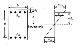
Method II. This method is based on the assumption that neutral axis of the homogeneous section, always passes through the C.G. of the section. Hence the moment of the transformed areas above and below the neutral axis (N.A.) of the R.C beam (moments being taken about the neutral axis) must be equal.
Therefore, equating the moment of compressive areas about N.A. to the moment of tensile area about N.A., we have
where = distance of the C.G. of compression steel from the extreme compression edge of the beam.
If the area of tensile and compressive steel and the dimensions of the section are given, methods II should be adopted for finding out the neutral axis of the section.
18.5 MOMENT OF RESISTNCE
The moment of resistance ( of a doubly-reinforced beam can be determined by taking moments of compressive forces in concrete and compression steel about the C.G. of the tensile reinforcement
We are given
![]()
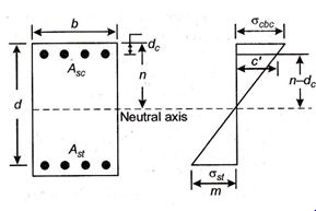
Referring to the stress diagram Fig. 18.1, we find that
or
![]()
From the review of the expression for the moment of resistance, it is observed that the moment of resistance of a doubly reinforced beam consists of two components:
(i) ![]() i.e., the moment of the compressive force in concrete about the C.G. of the tensile steel. This component thus represents the moment of resistance of a singly-reinforced beam without any compression reinforcement. Let us denote it by M1.
i.e., the moment of the compressive force in concrete about the C.G. of the tensile steel. This component thus represents the moment of resistance of a singly-reinforced beam without any compression reinforcement. Let us denote it by M1.
(ii) ![]() i.e., the moment of compressive force in steel is compression about the C.G. of the tensile steel. This component thus represents the moment which the beam can resist in excess of M1. Let us denote it by M2.
i.e., the moment of compressive force in steel is compression about the C.G. of the tensile steel. This component thus represents the moment which the beam can resist in excess of M1. Let us denote it by M2.
\[{M_r}={M_1}{M_2}\]
Let
![]() = the area of tensile steel required for the balanced section corresponding to the moment M1. And
= the area of tensile steel required for the balanced section corresponding to the moment M1. And
and ![]() = the area of additional tensile steel required to develop the moment M2.
= the area of additional tensile steel required to develop the moment M2.
Thus
\[{A_{st}}_1={{{M_1}} \over {{\sigma _{st}} \times Leverarm}}={{{M_1}} \over {{j_1}d{\sigma _{st}}}}\]
and
\[{A_{st}}_2={{{M_1}} \over {{\sigma _{st}} \times Leverarm}}={{{M_2}} \over {{\sigma _{st\left( {d - {d_c}} \right)}}}}\]
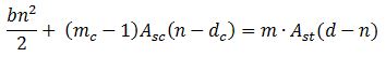
It may be noted that the additional tensile steel is actually required to balance the steel in compression. Hence can also be calculated alternatively by taking moment of the equivalent concrete area of compression steel and the moment of the equivalent concrete area of additional tensile steel ( about the neutral axis
\[m.{A_{st}}_2\left( {d - n} \right)=\left( {{m_c} - 1} \right){A_{sc}}\left( {n - {d_c}} \right)\]
or \[{A_{st}}_2={{\left( {1.5m - 1} \right){A_{sc}}\left( {n - {d_c}} \right)} \over {m\left( {d - n} \right)}}\]
Hence total tensile steel required for the section \[{A_{st}}={A_{st}}_1 + {A_{st}}_2\]
In the expression for moment of resistance the value of (c) stress in concrete to be adopted will depend upon the position of neutral axis of the section. In case of a balanced section, the value of c will be =\[{\sigma _{cbc}}\] . The value of c will work out to be less than the permissible stress in concrete \[{\sigma _{cbc}}\] in the following two cases.
Case (a) In this case the area of the tensile steel provided may be insufficient to balance even the compressive stress in concrete. Thus steel attains its maximum permissible tensile stress first and the concrete will not be subjected to full value of permissible compressive stress. The neutral axis in such a case will be above the critical neutral axis nc.
Case (b) In this case, the area of compression steel provided may be more than that required to balance the additional tensile reinforcement (\[{A_{st}}_2\]). Hence the stress in tensile steel will attain its maximum permissible tensile stress first and the neutral axis will lie above the critical neutral axis (nc).
Hence in all such cases where the actual N.A. lies about the critical axis (i.e. nc), the concrete will not be subjected to its full permissible stress and the value (c) should be worked out form the following relation
\[{c \over {t/m}}={n \over {d - n}}\]
or
\[c={t \over m}{n \over {\left( {d - n} \right)}}={{{\sigma _{st}}} \over m}.{n \over {\left( {d - n} \right)}}\]
18.6 STEEL BEAM THEORY
In the design of doubly reinforced beam by steel beam theory, equal area of tensile and compression steel is provided and the total compressive force is assumed to be resisted by the compression steel. Thus in this method, the concrete is altogether neglected both in compression as well as in tension zone. The area of compression at top and tension steel at the bottom of the beam act like the top and bottom flanges of an imaginary rolled steel joist (R.S.J) the concrete between them acting as an imaginary web of the R.S.J. Thus the lever arm in this case becomes equal to the centre to centre distance between the compression and tension steel.
Hence the moment of resistance of the section in the case is given
\[{M_r}={\sigma _{st}}{A_{st}}\left( {d - {d_c}} \right)\]
Last modified: Saturday, 5 October 2013, 8:36 AM