Site pages
Current course
Participants
General
MODULE 1. Electro motive force, reluctance, laws o...
MODULE 2. Hysteresis and eddy current losses
MODULE 3. Transformer: principle of working, const...
MODULE 4. EMF equation, phase diagram on load, lea...
MODULE 5. Power and energy efficiency, open circui...
MODULE 6. Operation and performance of DC machine ...
MODULE 7. EMF and torque equations, armature react...
MODULE 8. DC motor characteristics, starting of sh...
MODULE 9. Polyphase systems, generation - three ph...
MODULE 10. Polyphase induction motor: construction...
MODULE 11. Phase diagram, effect of rotor resistan...
MODULE 12. Single phase induction motor: double fi...
MODULE 13. Disadvantage of low power factor and po...
MODULE 14. Various methods of single and three pha...
LESSON 13. DC generators and their characteristics - Armature reaction and commutation
Types of generators
There are three general types of generator in common use, the shunt, the compound and the series. In the shunt type (Fig. 7. 5) the field circuit is connected across the armature terminals, usually in series with a rheostat. The shunt field, therefore, must have a comparatively high resistance that it does not take too great a proportion of the generator current. The compound generator is similar to the shunt, but has an additional field winding connected in series with the armature or load. The series generator is excited entirely by a winding of comparatively fewer turns connected in series with the armature and load.
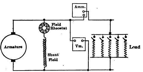
Fig. 7. 5 Shunt generator connections.
Shunt Generator.
Fig. 7. 6 below shows the saturation curve of a shunt generator and its shunt field resistance line drawn on the same plot. This field has a resistance of 24 ohms, so that at 120 volts it takes 5 amp and so on. At the instant of starting a generator the induced voltage is zero. As the generator is brought up to speed there will be small voltage ‘oa’, here about 4 volts, induced in the armature due to the residual magnetism of the machine. This exists across the shunt field coil, because it is connected across the armature terminals. The resulting field current due to this voltage is obtained by drawing a horizontal line from a until it meets the field resistance line at b. The current in this particular case is ob' or about 0.2 ampere. By looking at the saturation curve, it is seen that for this field current, the induced voltage, b'c, is about 8 volts. The 8 volts produces about 0.33 ampere in the field, as may be seen by projecting across to the field resistance line at d. This field current od’ produces a voltage d'e, which in turn produces a higher value of field current. Thus each value of field current produces a voltage in excess of its previous value and this increased voltage in turn increases the field current, which is cumulative. The machine will continue to build up until point ‘f’ is reached, where the field resistance line crosses the saturation curve. The machine will not build up beyond this point for the following reasons:
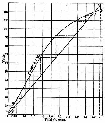
Fig. 7.6 Method of shunt generator building up.
Critical field resistance
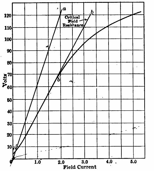
If the resistance of the field be increased to say 60 ohms, the field resistance line will be represented by oa in Fig. 7.7. This line crosses the saturation curve at point a', corresponding to about 6 volts. Therefore, with this value of field resistance, the generator will not build up beyond a'. If the field resistance be slowly decreased until the field resistance line reaches ob, the generator will start building up rapidly. It will of course stop building up voltage at the point b'. The value of the field resistance corresponding to ob is called the critical field resistance. In this particular case the resistance is 120/3.25 or 36.1 ohms.
Armature Reaction
|
Critical field resistance |
The next Fig. 7.8 shows the flux passing from the field poles through an armature when there is no current in the armature conductors. This flux is produced entirely by the ampere-turns of the field. The neutral plane, which is a plane perpendicular to the flux, coincides with the geometrical neutral axis of the poles. At the right is shown a vector F which represents the mmf. producing this flux, in magnitude and direction. At right angles to this vector F is the neutral plane.
In figure 7.8 (b), there is no current in the field coils, but the armature conductors are shown as carrying current. This current is in the same direction in the armature conductors as it would be were the generator under load. The current obviously flows in the same direction in all the conductors that lie under one pole. The current is shown as flowing into the paper on the left-hand side of the armature. (This current direction as obtained by Fleming's right-hand rule). These conductors combine their mmf.'s to send a flux downward through the armature, as shown in the diagram 7.8 (b), this direction determined by the corkscrew rule. The conductors on the right-hand side of the armature are shown as carrying current coming out of the paper. They also combine their mmf.'s to send a flux downward through the armature. The conductors on both sides of the armature combine their mmfs in such a manner as to send flux down through the armature. The direction of this flux is perpendicular to the polar axis. To the right of the figure the armature mmf. is represented in direction and magnitude by the vector FA. Figure (c) shows the result obtained when the field current and the armature current are acting simultaneously, which occurs when the generator is under load.
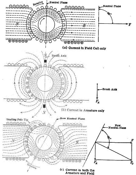
Fig. 7.8 Effect of armature reaction upon the field of a generator.
The armature emf crowds the symmetrical field flux shown in 7.8 (a) into the upper pole tip in the north pole and into the lower pole tip in the south pole. As the generator armature is shown rotating in a clockwise direction, the flux is crowded into the trailing pole tip and is weakened in the two leading pole tips.
To the right of figure 7.8 (c), the armature reaction is as vectors. The field vector F and the armature vector FA add to form the resultant field vector F0. The direction of F0 is downward and to the right, which corresponds to the general direction of the resultant flux. As the magnetic neutral plane is perpendicular to the resultant field and hence has turned angularly. But we know that the brushes should be set so that they short-circuit the coil undergoing commutation as it is passing through the neutral plane.
As the load current varies, depending on its magnitude will be shifting the magnetic neutral plane accordingly. So the brushes if placed at the original geometric neutral plane would commute the armature when there is a current in the conductors resulting in sparking and subsequent pitting of commutator. If the brushes are advanced to correspond to the advance of the neutral plane, all the conductors to the left of the two brushes must still carry current into the paper, and those to the right must carry current out of the paper. The direction of the armature field moves with the brushes. Its axis always lies along the brush axis. Therefore FA, instead of pointing vertically downward, now points downward and to the left, as is shown by the vectors. FA may be resolved into two components, FD parallel to the polar axis and Fc perpendicular to this axis. FD acts in direct opposition to FA, the main field and reduces the total flux and so is called the demagnetizing component of armature reaction (Fig. 7.9). Fc acts at right angles to F and produces distortion and is called the cross-magnetizing component of armature reaction.
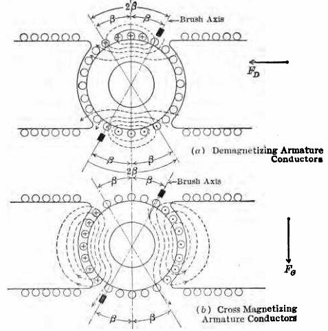
Fig. 7.9 Demagnetizing and cross-magnetizing components of armature reaction