Site pages
Current course
Participants
General
MODULE 1. Electro motive force, reluctance, laws o...
MODULE 2. Hysteresis and eddy current losses
MODULE 3. Transformer: principle of working, const...
MODULE 4. EMF equation, phase diagram on load, lea...
MODULE 5. Power and energy efficiency, open circui...
MODULE 6. Operation and performance of DC machine ...
MODULE 7. EMF and torque equations, armature react...
MODULE 8. DC motor characteristics, starting of sh...
MODULE 9. Polyphase systems, generation - three ph...
MODULE 10. Polyphase induction motor: construction...
MODULE 11. Phase diagram, effect of rotor resistan...
MODULE 12. Single phase induction motor: double fi...
MODULE 13. Disadvantage of low power factor and po...
MODULE 14. Various methods of single and three pha...
LESSON 15. Compound and Series generators
The Compound Generator:
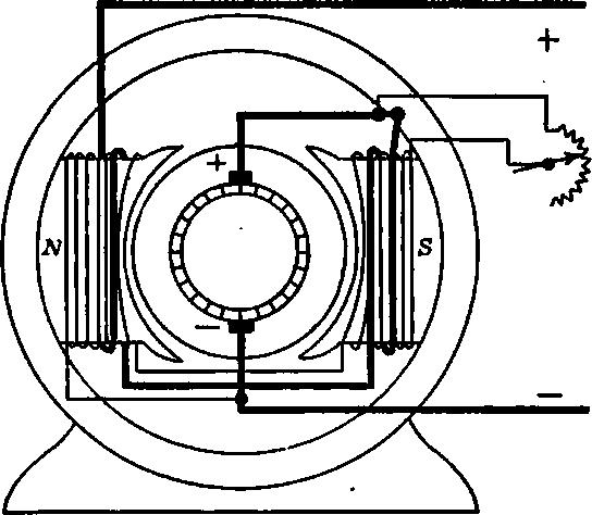
Fig. 7.15 Compound generator connections.
The drop in voltage with load, which is characteristic of the shunt generator, makes this type of generator undesirable where constant voltage is essential. This applies particularly to lighting circuits, where a very slight change of voltage makes a material change in the power of lamps. A generator may be made to produce a substantially constant voltage, or even a rise in voltage as the load increases, by placing on the field core a few turns which are connected in series with the load.
These turns are connected' so as to aid the shunt turns when the generator ers current. As the load increases,the current through the series turns also increases and, therefore, the flux through the armature increases. The effect of this increased flux is to increase the induced voltage. By proper adjustment of the series ampere-turns, this increase in armature voltage is made to balance the drop in voltage due to armature reaction and that due to the resistance drop in the armature. If the terminal voltage is maintained substantially constant, the field current will not drop as the load increases. Therefore, the three causes of voltage drop, namely, armature reaction, IaR drop, and drop in field current, are neutralized more or less completely by the effect of the series ampere-turns.
The shunt field may be connected directly across the armature terminals, Fig.7.15 (a) above, in which case the machine is called short shunt. If the shunt field be connected across the machine terminals outside the series field, as in fig 7.15 (b), the machine is long shunt. The operating characteristic is about the same in either case (Fig. 7.16).
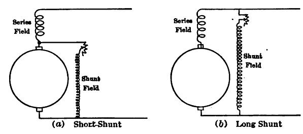
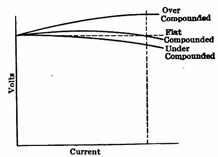
Fig. 7.16 Compound generator Characteristics
If the effect of the series turns is to produce the same voltage at rated load as at no load, the machine is said to be flat compounded. It is seldom possible to maintain a constant voltage for all values of current from no load to rated load. The tendency is for the voltage first to rise and then to drop again, reaching the same voltage at rated load as was obtained at no load. The particular shape of the characteristic is due to the iron becoming saturated, so that the added series ampere-turns do not increase the flux at full load as much as they do at light load. When the rated-load voltage is greater than the no-load voltage, the machine is said to be over compounded. When the rated-load voltage is less than the no-load voltage, the machine is said to be under compounded. Generators are seldom under compounded. Flat-compounded generators are used principally in isolated plants, such as hotels and office buildings. Over-compounded generators are used where the load is located at some distance from the generator. As the load increases, the voltage at the load tends to decrease, due to the voltage drop in the feeder. If, however, the generator voltage rises just enough to offset this feeder drop, the voltage at the load remains constant.
In a compound generator the induced voltage in the armature is:
. . E = V + IaRa + IfRf
where V is the terminal voltage, If the series field current, Ia the armature current, and Rf and Ra the series field and armature resistance respectively. In a long shunt generator If = Ia.
Example.—A compound generator, connected short shunt, has a terminal voltage of 230 volts when it is delivering a current of 150 amp. The shunt field current is 4 amp, the armature resistance 0.03 ohm and the series field resistance 0.01 ohm. Determine the induced voltage in the armature, the total power generated in the armature.
The series field current If = 150 amp., and the armature current Ia = 154 amp.
E = 230 + (150 × 0.01) + (154 × 0.03) = 236.1 volts.
Total power generated
Pa = 236.1 × 154 = 36,400 watts = 36.4 kw.
Armature loss
Pa = 1542 × 0.03 = 711 watts.
Series field loss
Pf = 1502 × 0.01 = 225 watts.
Shunt field loss
Psh = (230 +1.5)4 = 926 watts.
Power delivered
P = 230 × 150 = 34,500 watts.
Effect of Speed
Fig. 7.17 shows the saturation curve of a 230-volt, compound generator, taken at
900 r.p.m
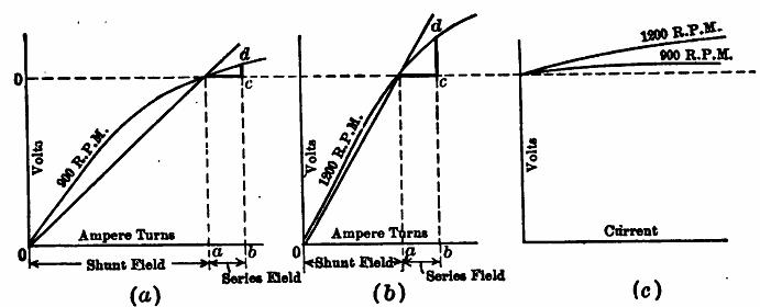
Fig. 7.17 Effect of speed upon compound characteristic.
The shunt field rheostat is so adjusted that the machine builds up to a no-load voltage of 230 volts. To produce this result a certain number of shunt field ampere-turns are necessary, as indicated by the distance ‘oa’. When load is applied to the machine a certain number of series ampere-turns are added. Let the number of series ampere-turns be represented by the distance ‘ab’. Neglecting armature reaction, the induced voltage will be increased by a value ‘cd’ shown in heavy lines. Let this same machine be speeded up to 1,200 r.p.m (Fig. 7.17 (b)), and let the no-load terminal voltage still be 230 volts. The distance ‘oa’ will now be less than it was in (Fig. 7.17 (a)), owing to the increased speed. But the distance ‘ab’ will be the same in each case, as the increase of series turns depends solely on the load. The increase of voltage ‘cd’ is much greater in (Fig. 7.17 (b)) than in (Fig. 7.17 (a)), owing to the lesser saturation of the iron. Therefore, the higher speed machine will have the more rising characteristic, as is shown in (Fig. 7.17 (c)). It will be noted that the effect of speed upon the compound characteristic is just opposite to the effect of speed upon the shunt characteristic. This is due to the fact that saturation opposes change of the flux in each case.
The Series Generator:
In the series generator the field winding is connected in series with the armature and the external circuit. It must consist necessarily of a comparatively few turns of wire having a sufficiently large cross-section to carry the rated current of the generator. The series generator in most instances is used for constant current work, in distinction to the shunt generator which maintains constant potential. Fig.7.18 shows the saturation curve of a series generator and also it’s characteristic. The saturation curve differs in no way from that of the shunt generator. The external characteristic is similar in shape to the saturation curve for low saturation. The voltage at each point is less than that shown
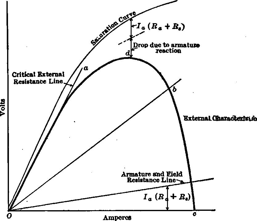
Fig. 7.18 Series generator characteristic.
by the saturation curve by the amount due to the drop through the armature and field Ia (Ra +Rf ) and the drop due to armature reaction. The curve reaches a maximum beyond which armature reaction becomes so great as to cause the curve to droop sharply and the voltage drops rapidly to zero. These machines are designed to have a very high value of armature reaction.
The machine builds up as follows: If the series field is connected in such a manner that the current due to the residual magnetism aids this residual magnetism, the generator will build up, provided the external resistance equals or is less than that indicated by the external resistance line ‘Oa’. The line ‘Oa’ is therefore called the critical external resistance line. As the external resistance decreases, the external resistance line swings down to the right. The line ‘ob’ is such a line. It would be practically impossible to operate with an external resistance corresponding to the line ‘Oa’, or to any line cutting the curve to the left of ‘d’, as a small increase in external resistance would swing the resistance line away from the curve resulting in the generator's dropping its load. The machine is designed to operate along the portion ‘bc’ of the curve, which corresponds to substantially constant current. The current is not affected by a considerable change in external resistance, corresponding to the line ‘Ob’ swinging up or down. To obtain close regulation the series field is shunted by a rheostat. The resistance of this rheostat is controlled by a solenoid connected in series with the line. In this way the current delivered by the generator may be held substantially constant. In the past, the series generator was much used in arc lighting.