Site pages
Current course
Participants
General
MODULE 1. Electro motive force, reluctance, laws o...
MODULE 2. Hysteresis and eddy current losses
MODULE 3. Transformer: principle of working, const...
MODULE 4. EMF equation, phase diagram on load, lea...
MODULE 5. Power and energy efficiency, open circui...
MODULE 6. Operation and performance of DC machine ...
MODULE 7. EMF and torque equations, armature react...
MODULE 8. DC motor characteristics, starting of sh...
MODULE 9. Polyphase systems, generation - three ph...
MODULE 10. Polyphase induction motor: construction...
MODULE 11. Phase diagram, effect of rotor resistan...
MODULE 12. Single phase induction motor: double fi...
MODULE 13. Disadvantage of low power factor and po...
MODULE 14. Various methods of single and three pha...
LESSON 31. Various methods of single phase power measurement
The Wattmeter
Alternating current power is equal to the product of the effective current and the effective volt age only when the power factor is unity. Therefore, the ammeter and voltmeter method, as used with direct currents, can seldom be used to measure alternating-current power. Consequently, a wattmeter is necessary for measuring alternating-current power. The wattmeter shown below operates on the electro-dynamometer principle. M is a moving coil wound with fine wire and is practically identical with the moving coil of the dynamometer voltmeter.
It is connected across the line in series with a high resistance. The current is led into this coil through springs. The two fixed coils FF are wound with a few turns of heavy wire, capable of carrying the load current. As there is no iron present, the field due to the current coils FF is proportional to the load current at every instant. The current in the moving coil M is proportional to the voltage at every instant. 'Therefore, for any given position of the moving coil, the torque is proportional at every instant to the product of the current and voltage or to the instantaneous power of the circuit. If the power factor is other than unity, there is negative torque for part of the cycle. That is, during the periods when there are negative loops in the power curve, the current in the fixed coil and the current in the moving coil reverse their directions with respect to each other, and so produce a negative torque. The moving coil takes a position corresponding to the average torque. The torque is also a function of the angle between the fixed and moving coil axes, but this factor is taken into account by the scale calibration.
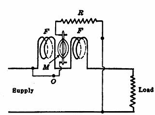
Fig. 14.1 Wattmeter
As the torque acting on the moving coil varies from instant to instant, having a frequency twice that of either the current or the voltage, the coil tends to change its position to correspond with these variations of torque. If the moving system had little inertia, the needle would vibrate so that it would be impossible to obtain a reading. Because of the relatively large moment of inertia of the moving system, the needle assumes a steady deflection for constant values of average power. The position taken by the coil corresponds to the average value of the power, which is the result desired.
Wattmeter Connections Figure 14.2 shows wattmeter W measuring the power taken by a certain load. In order to measure this power correctly, the wattmeter current coil should
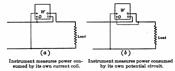
Fig. 14.2 Wattmeter connections
carry the load current, and the wattmeter voltage-coil, in series with its resistance, should be connected directly across the load. The current in the wattmeter current coil is the same as the load current, but the wattmeter potential circuit is not connected directly across the load, but is measuring a potential in excess of the load potential by the amount of the impedance drop in the wattmeter current-coil. Therefore, the wattmeter reads too high by the amount of power consumed in its own current-coil.
Under these conditions the true power
P = P' – I2Rc
where P' is the power indicated by the wattmeter, I is the current in the wattmeter current coil, and Rc is the resistance of this coil. This loss is ordinarily of the magnitude of 1 or 2 watts at the rated current of the instrument, and may often be neglected.
If the wattmeter be connected as shown in (b), the wattmeter potential circuit is connected directly across the load, but the wattmeter current coil carries the potential coil current in addition to the load current. In fact, the wattmeter potential circuit may be considered as being a small load connected in parallel with the actual load whose power is to be measured. Therefore, the power consumed by this potential circuit must be deducted from the wattmeter reading. The true power taken bv the load,
P = P' - E2/Rc
where P' is the wattmeter reading, E the load voltage and Rc the resistance of the wattmeter potential coil circuit. An idea of the magnitude of this correction may be obtained from the following example.
Example.—A certain wattmeter indicates 157 watts when it is connected in the manner shown in figure (b). The line voltage is 120 volts and the resistance of the wattmeter potential circuit is 2,000 ohms. How much power is taken by the load?
P = 157 - 1202/2,000 = 149.8 watts.
It will be observed that a considerable percentage error would result in this case if the wattmeter loss were neglected. The instrument is so manufactured which compensates for this loss. A small auxiliary coil, connected in series with the moving-coil system, is inter wound with the fixed coils so that a small counter-torque is exerted, this counter torque being proportional to the power consumed by the potential circuit.
The current and potential circuits of a wattmeter must each have a rating corresponding to the current and voltage of the circuit to which the wattmeter is connected. A wattmeter is rated in amperes and volts, rather than in watts, because the indicated watts show neither the amperes in the current-coil nor the voltage across the potential-circuit.
If the current in an ammeter or the voltage across a voltmeter exceed the rating of the instrument, the pointer goes off scale and so warns the user. A wattmeter may be considerably overloaded and yet the load power factor be so low that the needle is well on the scale. For this reason a voltmeter and an ammeter should ordinarily be used in conjunction with a wattmeter (Fig. 14.3) so that it is possible to determine whether either the voltage or the current exceeds the wattmeter rating.
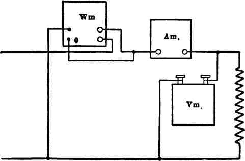
Fig. 14.3 Wattmeter, ammeter and voltmeter connections for measuring power